Copyright © 1996 General Motors Corp. 7–9
ASSEMBLY OF TRANSMISSION
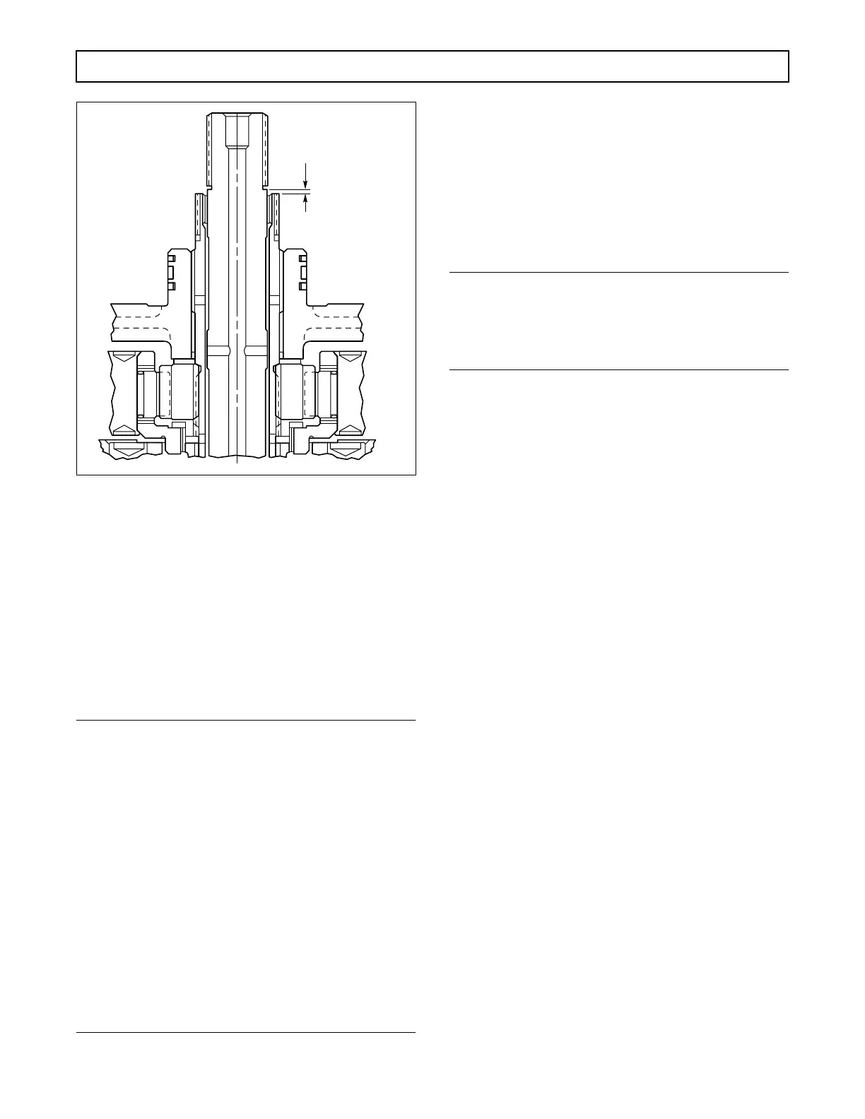
Figure 7–18. Sun Gear Shaft Clearance
(3) Install the fourth clutch assembly (as re-
built in Paragraph 6–12) onto the splines of the sun
gear shaft.
7–7. INSTALLATION OF THIRD AND
FORWARD CLUTCHES
a. Third Clutch
(Foldout 9,B)
NOTE:
Establishing clutch clearance for the third clutch
pack by stack dimension is not necessary. The run-
ning clearance for this clutch is such that it will ac-
cept all internal and external plates within their
required wear limit. (Refer to Section 8.) However,
especially for models with retarder, it is critical that
the wear limits measurements are taken and that
the third-clutch plates are within the wear limits
listed in Section 8. The retarder housing serves as a
backplate for the third clutch pack, making the
pack inaccessible for a running clearance check
when the third clutch pack is first installed. Third
clutch running clearance for models with retarder
is not checked until the transmission is removed
from the overhaul stand. Refer to Paragraph 7–12
b
.
(1) Beginning with an external-tanged clutch
plate, alternately install three (models without re-
tarder) or four (models with retarder) external-tanged
and three internal-splined plates (Figure 7–19). Note
the location of the three pairs of tangs and a single
tang in relation to paired slots and a single slot. The
plate will have minimal rotational movement when
properly installed.
NOTE:
•
For models without retarder, proceed with Step (2).
•
For models with retarder, skip Steps (2) through
(5) and proceed with Paragraph 7–7
b
.
(2) Install the third clutch backplate, align-
ing its tangs with those of the three clutch plates
(Figure 7–20). For models prior to S/N 3210668026,
this plate is identified by the Mark
4
. For later mod-
els, there is a square stamped on a single external
tang.
(3) Install the snapring that retains the back-
plate (Figure 7–20). The snapring is identified by a
green mark and is 0.155–0.157 inch (3.94–3.99 mm)
thick. The snapring gap must be at the 12 o'clock posi-
tion (viewed from the front of the transmission hous-
ing), and must be fully seated in its groove.
(4) Using third clutch clearance gauge
J 23716 (Figure 7–20), check the clutch running clear-
ance. The thin end of the gauge should pass between
the snapring and the backplate; the thick end should
not. The running clearance is correct with a dimension
of 0.028–0.119 inch (0.74–3.02 mm).
(5) If clearance is excessive (larger end of
gauge enters plates), new clutch plates should replace
worn plates. Refer to the wear limits in Section 8 for
clutch plate dimensions.
(6) Skip Paragraph 7–7
b
and proceed with
Paragraph 7–7
c
.
b. Retarder Housing Assembly.
Install the re-
tarder housing assembly, stator blades upward, align-
ing the oil jumper tube holes with the PTO opening in
the transmission housing (Figure 7–21).
V02989
APPROX.
1
⁄8 in. (3.18 mm)
 Loading...


