7–8 Copyright © 1996 General Motors Corp.
AT 500, 1500 SERIES AUTOMATIC TRANSMISSIONS
(8) Check the end play of the transmission
output shaft as follows.
(9) Place the first clutch spring compressor
base J 23630-2, flange side down on the output shaft
(Figure 7–16). Secure the base to the output shaft with
a
1
⁄
2
-20 x 1
1
⁄
4
inch bolt. Tighten the bolt to 15 lb ft
(20 N
.
m).
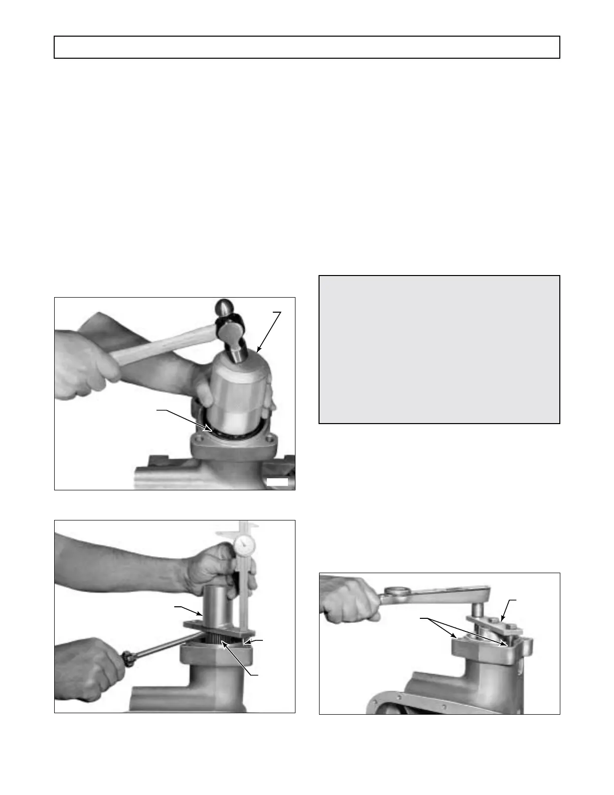
(10) Lift the output shaft with a screwdriver
(Figure 7–16) and measure the distance from the top
of the flange to the rear of the transmission. Release
the output shaft and repeat the measurement. The al-
lowable clearance with the proper spacer is 0.013–
0.031 inch (0.33–0.79 mm).
A different size spacer
must be used if this clearance is not obtained
.
Figure 7–15. Installing Rear Output Shaft Bearing
Figure 7–16. Checking End Play of
Output Shaft
(11) Install spring compressor assembly
J 23630-2. Tighten the
1
⁄
2
-20 x 1
1
⁄
4
inch center bolt to
15 lb ft (20 N·m). Align the spring compressor base
with the two parking brake mounting holes in the
transmission housing (Figure 7–17). Install two
1
⁄
2
-13
bolts through the base and into the case. Tighten these
bolts evenly to 5–8 lb ft (7–11 N·m). This positions the
gear pack and all components for an accurate selective
thrust washer measurement in Paragraph 7–8.
b. Fourth Clutch
(Foldout 9,A)
(1) Reposition the transmission, front up-
ward. Carefully remove sun gear shaft retainer J 24352
or J 39736-01 (Figure 7–12) without moving the sun
gear shaft.
(2) If the sun gear shaft assembly is properly
seated, there should be approximately
1
⁄
8
inch (3.18 mm)
distance from the end of the sun gear shaft assembly to
the shoulder on the main shaft shown in Figure 7–18.
If the shaft is not properly seated, a slow rotation with
a slight up and down motion may seat it. If not, re-
move the shaft (noting its relative position to the main
shaft) and center the front sun gear thrust washer so
the sun gear shaft will bottom. Recheck the clearance
(Figure 7–18).
Figure 7–17. Positioning Components For
Front Thrust Washer Measurements
H02986
BEARING
J 24446
H02987
OUTPUT
SHAFT
DEPTH
GAUGE
J 23630-2
CAUTION:
•
The sun gear shaft assembly must be properly
seated to establish an accurate clearance be-
tween the forward clutch housing and the
front support and bearing assembly. Refer to
Paragraph 7–8.
•
Do not remove
the sun gear shaft assembly be-
fore checking the required clearance shown on
Figure 7–18. If the clearance is less than
1
⁄
8
inch (3.18 mm), proceed with Step (2). Other-
wise, skip Step (2) and proceed with Step (3).
H02988
PARKING
BRAKE
MOUNTING
HOLES
J 23630-02
 Loading...


