Copyright © 1996 General Motors Corp. 7–7
ASSEMBLY OF TRANSMISSION
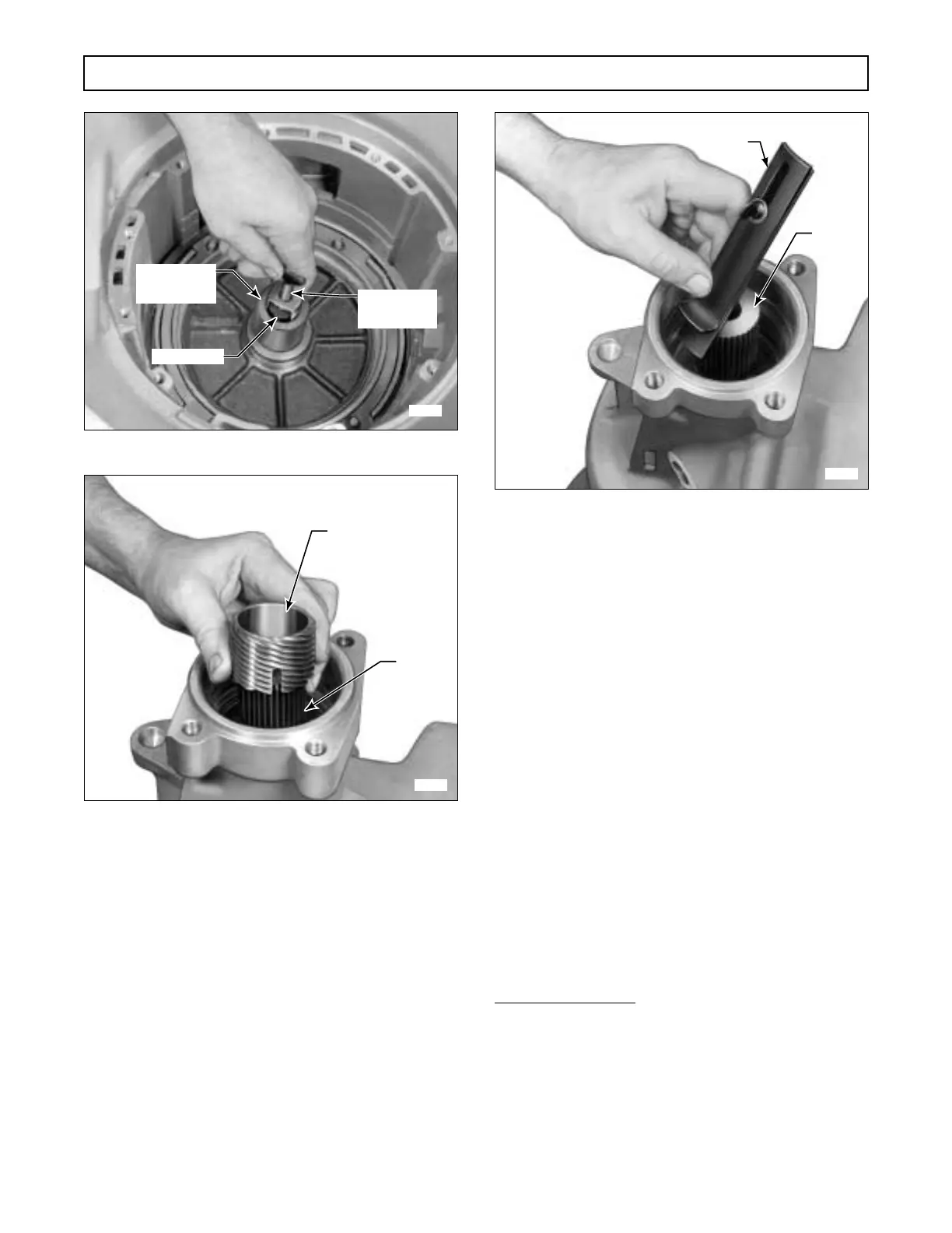
Figure 7–12. Installing Sun Gear Shaft Retainer
Figure 7–13. Installing Governor Drive Gear
(4) Using a soft drift, tap against the speed-
ometer drive gear or speed sensor wheel to seat all the
installed components.
(5) Loosen the thumbscrew on spacer selec-
tion gauge J 23632-01 and position the gauge against
the output shaft (Figure 7–14). Push the straight mem-
ber of the gauge against the rear of the speedometer
drive gear. Push the lipped member against the rear
bearing front snapring. It may be necessary to extend
the slot on the gauge to obtain this measurement.
When the gauge is in firm contact with these parts, and
the concave side of the straight member is firmly
against the output shaft, tighten the thumbscrew.
Figure 7–14. Measuring For Selection of
Rear Bearing Spacer
(6) Remove the gauge, and using a depth mi-
crometer, measure the distance from the end of the
straight member to the lip of the curved member. Use
this dimension to select the proper rear spacer, as
listed in the following chart. Install the spacer.
*Dimension in inches (millimeters)
(7) Using bearing installer tool J 24446, in-
stall rear bearing 4 (Foldout 12,B) numbered side out,
as shown in Figure 7–15. Install beveled snapring 5
(Foldout 9,B), flat side down.
H02983
J 24352
(J 39736-01,
AT 1500 Series)
MAIN SHAFT
J 21795-4
(J 39736-02,
AT 1500 Series)
H02984
OUTPUT
SHAFT
GOVERNOR
DRIVE GEAR
Dimension* Use
SpacerFrom To Marked
1.0003 1.0138 23017123 1 Groove
(25.408) (25.750)
1.0138 1.0273 23017124 2 Grooves
(25.750) (26.093)
1.0273 1.0408 23017125 0 or 3 Grooves
(26.093) (26.436) (See SIL 20-TR-92)
1.0408 1.0543 23017126 4 Grooves
(26.436) (26.779)
1.0543 1.0678 23017127 5 Grooves
(26.779) (27.122)
1.0678 1.0813 23017128 6 Grooves
(27.122) (27.465)
H02985
OUTPUT
SHAFT
J 23632-01
 Loading...


