7–6 Copyright © 1996 General Motors Corp.
AT 500, 1500 SERIES AUTOMATIC TRANSMISSIONS
(7) Install center support compressor
J 23717-C (Figure 7–10). Use two of the
5
⁄
16
-18 x 1
3
⁄
4
inch oil pump assembly retaining bolts to retain the
compressor.
(8) Tighten the compressor bolt to 5 lb ft
(7 N·m) (Figure 7–10).
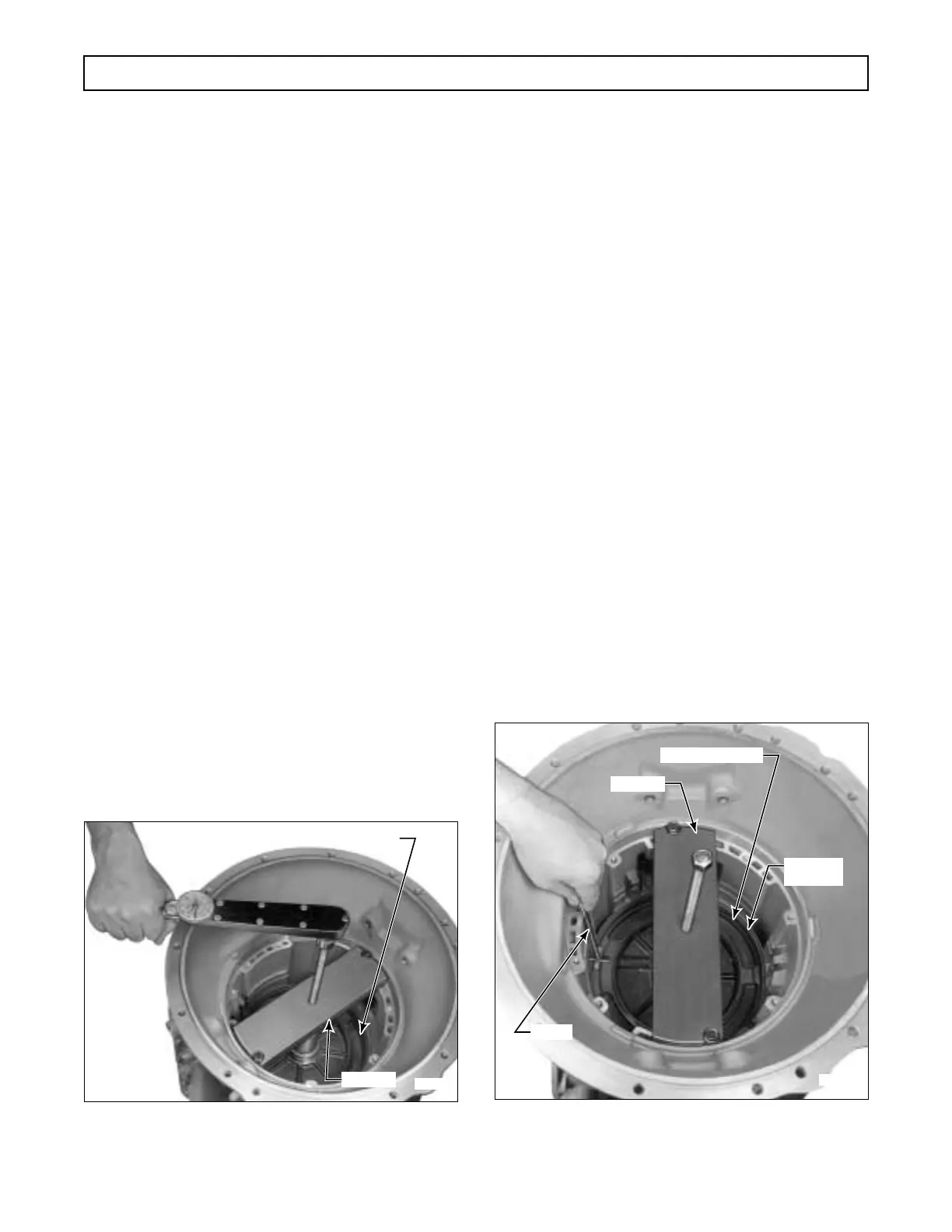
(9) Using snapring gauge J 34127, measure
the snapring groove clearance (Figure 7–11). The
gauge has four lugs of different thicknesses, with each
lug thickness stamped on the tool shaft. Try all four
lugs in the groove. The thickest lug which will enter
the groove indicates the thickness of the snapring re-
quired.
(10) Select a snapring from the list.
(11) Install the snapring selected in Step (10).
The snapring gap must be located at the 12 o’clock po-
sition (at the top of the transmission housing), and
must be fully seated in its groove.
Figure 7–10. Compressing Center Support For
Snapring Measurement
(12) Remove the center support compressor.
(13) Install two new hook-type sealrings 12
(Foldout 9,B) onto the hub of center support assem-
bly 13.
7–6. INSTALLATION OF REAR
BEARING SPACER AND
FOURTH CLUTCH
a. Selecting, Installing Rear Bearing Spacer
(Foldout 12,B)
(1) Install the sun gear shaft retainer J 24352
for AT 500 Series or J 39736-01 for AT 1500 Series
onto the transmission main shaft (Figure 7–12). Be
sure retainer sleeve is seated on the sun gear shaft
while tightening the thumb screw.
(2) Position the transmission, rear end up-
ward. Install the governor drive gear, engaging its slot
with the pin in the output shaft (Figure 7–13).
(3) Install speedometer drive gear 2 (Foldout
12,B) or speed sensor wheel 9 onto the output shaft.
Figure 7–11. Measuring For Selection of
Center Support Snapring
Gauge
Lug
Snapring
Color Code
Snapring
Thickness
0.149 inch Blue 0.148–0.150 inch
(3.78 mm) (3.76–3.81 mm)
0.153 inch Yellow 0.152–0.154 inch
(3.88 mm) (3.86–3.91 mm)
0.156 inch Green 0.155–0.157 inch
(3.96 mm) (3.94–3.99 mm)
0.159 inch Red 0.158–0.160 inch
(4.04 mm) (4.01–4.06 mm)
H02981
CENTER SUPPORT
J 23717-C
H02982
CENTER SUPPORT
J 23717-C
SNAPRING
GROOVE
J 34127
 Loading...


