Chapter 3
Using the DE1-SoC
Board
This chapter provides an instruction to use the board and describes the peripherals.
3
3
.
.
1
1
S
S
e
e
t
t
t
t
i
i
n
n
g
g
s
s
o
o
f
f
F
F
P
P
G
G
A
A
C
C
o
o
n
n
f
f
i
i
g
g
u
u
r
r
a
a
t
t
i
i
o
o
n
n
M
M
o
o
d
d
e
e
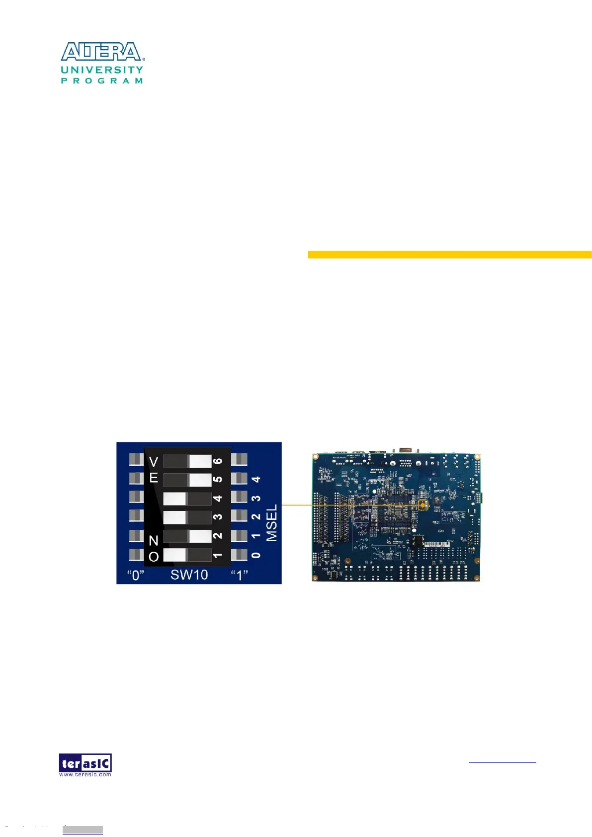
When the DE1-SoC board is powered on, the FPGA can be configured from EPCQ or HPS. The
MSEL[4:0] pins are used to select the configuration scheme. It is implemented as a 6-pin DIP
switch SW10 on the DE1-SoC board, as shown in Figure 3-1.
Figure 3-1 DIP switch (SW10) setting of Active Serial (AS) mode at the back of DE1-SoC board
Table 3-1 shows the relation between MSEL[4:0] and DIP switch (SW10).
Downloaded from Arrow.com.Downloaded from Arrow.com.Downloaded from Arrow.com.Downloaded from Arrow.com.Downloaded from Arrow.com.Downloaded from Arrow.com.Downloaded from Arrow.com.Downloaded from Arrow.com.Downloaded from Arrow.com.Downloaded from Arrow.com.Downloaded from Arrow.com.Downloaded from Arrow.com.Downloaded from Arrow.com.