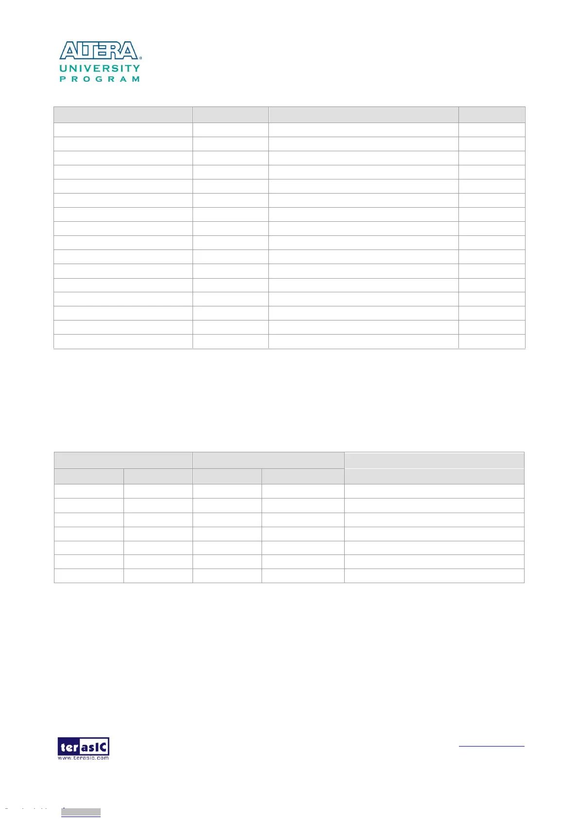
Table 3-24 Pin Assignment of Gigabit Ethernet PHY
GMII and MII transmit enable
GMII and MII receive data valid
GMII and MII receive data[0]
GMII and MII receive data[1]
GMII and MII receive data[2]
GMII and MII receive data[3]
GMII and MII receive clock
Management Data Clock Reference
Interrupt Open Drain Output
There are two LEDs, green LED (LEDG) and yellow LED (LEDY), which represent the status of
Ethernet PHY (KSZ9021RNI). The LED control signals are connected to the LEDs on the RJ45
connector. The state and definition of LEDG and LEDY are listed in Table 3-25. For instance, the
connection from board to Gigabit Ethernet is established once the LEDG lights on.
Table 3-25 State and Definition of LED Mode Pins
1000 Link / Activity (RX, TX)
100 Link / Activity (RX, TX)
10 Link / Activity (RX, TX)
The board has one UART interface connected for communication with the HPS. This interface
doesn’t support HW flow control signals. The physical interface is implemented by UART-USB
onboard bridge from a FT232R chip to the host with an USB Mini-B connector. More information
about the chip is available on the manufacturer’s website, or in the directory \Datasheets\UART TO
Downloaded from Arrow.com.Downloaded from Arrow.com.Downloaded from Arrow.com.Downloaded from Arrow.com.Downloaded from Arrow.com.Downloaded from Arrow.com.Downloaded from Arrow.com.Downloaded from Arrow.com.Downloaded from Arrow.com.Downloaded from Arrow.com.Downloaded from Arrow.com.Downloaded from Arrow.com.Downloaded from Arrow.com.Downloaded from Arrow.com.Downloaded from Arrow.com.Downloaded from Arrow.com.Downloaded from Arrow.com.Downloaded from Arrow.com.Downloaded from Arrow.com.Downloaded from Arrow.com.Downloaded from Arrow.com.Downloaded from Arrow.com.Downloaded from Arrow.com.Downloaded from Arrow.com.Downloaded from Arrow.com.Downloaded from Arrow.com.Downloaded from Arrow.com.Downloaded from Arrow.com.Downloaded from Arrow.com.Downloaded from Arrow.com.Downloaded from Arrow.com.Downloaded from Arrow.com.Downloaded from Arrow.com.Downloaded from Arrow.com.Downloaded from Arrow.com.Downloaded from Arrow.com.Downloaded from Arrow.com.Downloaded from Arrow.com.Downloaded from Arrow.com.Downloaded from Arrow.com.Downloaded from Arrow.com.Downloaded from Arrow.com.Downloaded from Arrow.com.Downloaded from Arrow.com.Downloaded from Arrow.com.Downloaded from Arrow.com.