3.6.12 A/D Converter and 2x5 Header
The DE1-SoC has an analog-to-digital converter (AD7928), which features lower power,
eight-channel CMOS 12-bit. This ADC offers conversion throughput rate up to 1MSPS. The analog
input range for all input channels can be 0 V to 2.5 V or 0 V to 5V, depending on the RANGE bit in
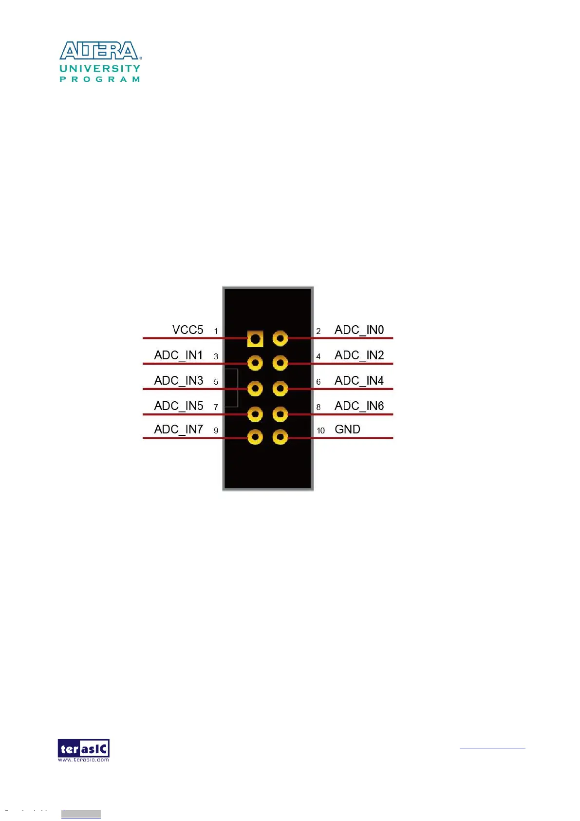
the control register. It can be configured to accept eight input signals at inputs ADC_IN0 through
ADC_IN7. These eight input signals are connected to a 2x5 header, as shown in Figure 3-29.
More information about the A/D converter chip is available in its datasheet. It can be found on
manufacturer’s website or in the directory \datasheet of De1-SoC system CD.
Figure 3-29 Signals of the 2x5 Header
Figure 3-30 shows the connections between the FPGA, 2x5 header, and the A/D converter.
Downloaded from Arrow.com.Downloaded from Arrow.com.Downloaded from Arrow.com.Downloaded from Arrow.com.Downloaded from Arrow.com.Downloaded from Arrow.com.Downloaded from Arrow.com.Downloaded from Arrow.com.Downloaded from Arrow.com.Downloaded from Arrow.com.Downloaded from Arrow.com.Downloaded from Arrow.com.Downloaded from Arrow.com.Downloaded from Arrow.com.Downloaded from Arrow.com.Downloaded from Arrow.com.Downloaded from Arrow.com.Downloaded from Arrow.com.Downloaded from Arrow.com.Downloaded from Arrow.com.Downloaded from Arrow.com.Downloaded from Arrow.com.Downloaded from Arrow.com.Downloaded from Arrow.com.Downloaded from Arrow.com.Downloaded from Arrow.com.Downloaded from Arrow.com.Downloaded from Arrow.com.Downloaded from Arrow.com.Downloaded from Arrow.com.Downloaded from Arrow.com.Downloaded from Arrow.com.Downloaded from Arrow.com.Downloaded from Arrow.com.Downloaded from Arrow.com.Downloaded from Arrow.com.Downloaded from Arrow.com.Downloaded from Arrow.com.Downloaded from Arrow.com.Downloaded from Arrow.com.Downloaded from Arrow.com.Downloaded from Arrow.com.Downloaded from Arrow.com.