3.6.1 User Push-buttons, Switches and LEDs
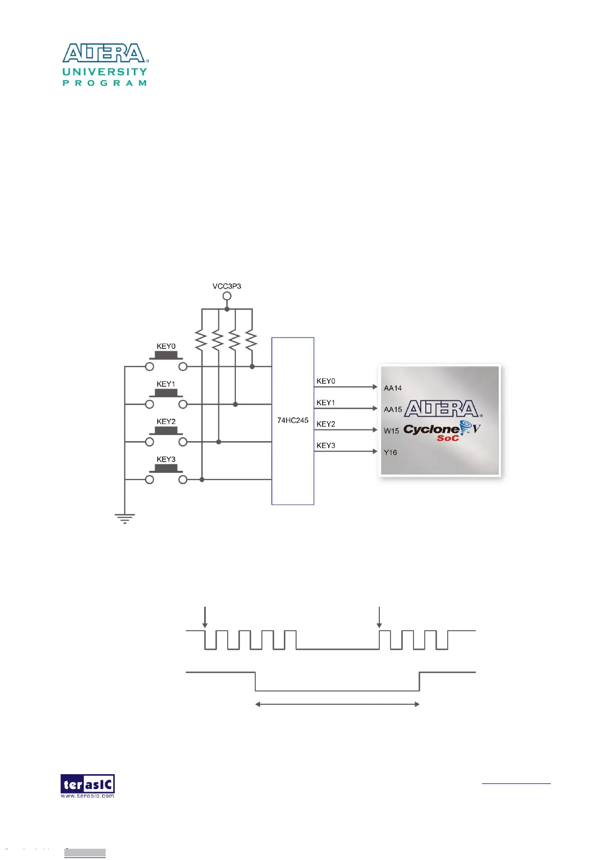
The board has four push-buttons connected to the FPGA, as shown in Figure 3-13 Connections
between the push-buttons and the Cyclone V SoC FPGA. Schmitt trigger circuit is implemented and act
as switch debounce in Figure 3-14 for the push-buttons connected. The four push-buttons named
KEY0, KEY1, KEY2, and KEY3 coming out of the Schmitt trigger device are connected directly to
the Cyclone V SoC FPGA. The push-button generates a low logic level or high logic level when it
is pressed or not, respectively. Since the push-buttons are debounced, they can be used as clock or
reset inputs in a circuit.
Figure 3-13 Connections between the push-buttons and the Cyclone V SoC FPGA
Pushbutton releasedPushbutton depressed
Before
Debouncing
Schmitt Trigger
Debounced
Figure 3-14 Switch debouncing
Downloaded from Arrow.com.Downloaded from Arrow.com.Downloaded from Arrow.com.Downloaded from Arrow.com.Downloaded from Arrow.com.Downloaded from Arrow.com.Downloaded from Arrow.com.Downloaded from Arrow.com.Downloaded from Arrow.com.Downloaded from Arrow.com.Downloaded from Arrow.com.Downloaded from Arrow.com.Downloaded from Arrow.com.Downloaded from Arrow.com.Downloaded from Arrow.com.Downloaded from Arrow.com.Downloaded from Arrow.com.Downloaded from Arrow.com.Downloaded from Arrow.com.Downloaded from Arrow.com.Downloaded from Arrow.com.Downloaded from Arrow.com.Downloaded from Arrow.com.Downloaded from Arrow.com.