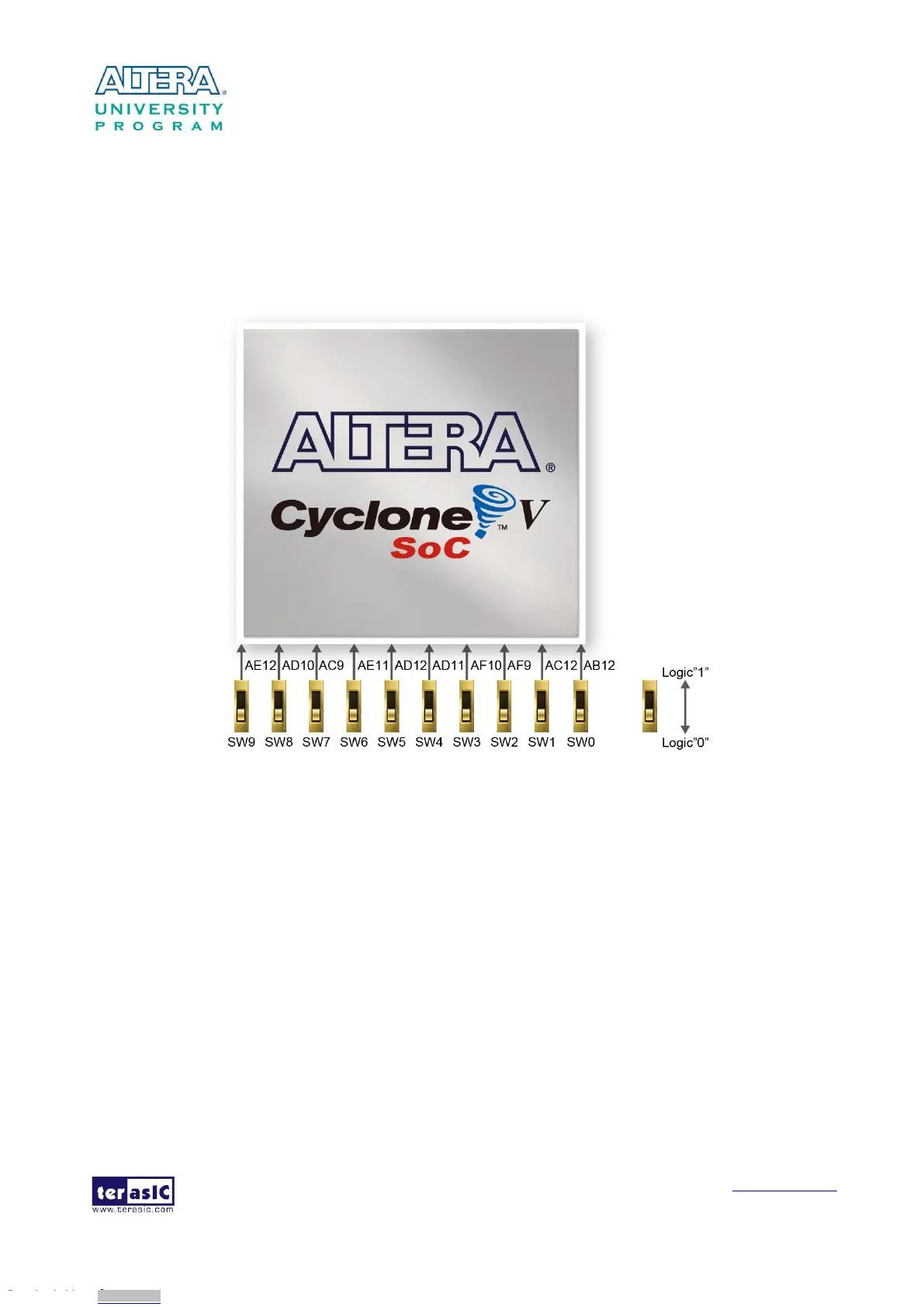
There are ten slide switches connected to the FPGA, as shown in Figure 3-15. These switches are
not debounced and to be used as level-sensitive data inputs to a circuit. Each switch is connected
directly and individually to the FPGA. When the switch is set to the DOWN position (towards the
edge of the board), it generates a low logic level to the FPGA. When the switch is set to the UP
position, a high logic level is generated to the FPGA.
Figure 3-15 Connections between the slide switches and the Cyclone V SoC FPGA
There are also ten user-controllable LEDs connected to the FPGA. Each LED is driven directly and
individually by the Cyclone V SoC FPGA; driving its associated pin to a high logic level or low
level to turn the LED on or off, respectively. Figure 3-16 shows the connections between LEDs and
Cyclone V SoC FPGA. Table 3-6, Table 3-7 and Table 3-8 list the pin assignment of user
push-buttons, switches, and LEDs.
Downloaded from Arrow.com.Downloaded from Arrow.com.Downloaded from Arrow.com.Downloaded from Arrow.com.Downloaded from Arrow.com.Downloaded from Arrow.com.Downloaded from Arrow.com.Downloaded from Arrow.com.Downloaded from Arrow.com.Downloaded from Arrow.com.Downloaded from Arrow.com.Downloaded from Arrow.com.Downloaded from Arrow.com.Downloaded from Arrow.com.Downloaded from Arrow.com.Downloaded from Arrow.com.Downloaded from Arrow.com.Downloaded from Arrow.com.Downloaded from Arrow.com.Downloaded from Arrow.com.Downloaded from Arrow.com.Downloaded from Arrow.com.Downloaded from Arrow.com.Downloaded from Arrow.com.Downloaded from Arrow.com.