User Manual – Rev AV AMETEK Programmable Power
MX Series 150
5. Principle of Operation
5.1 General
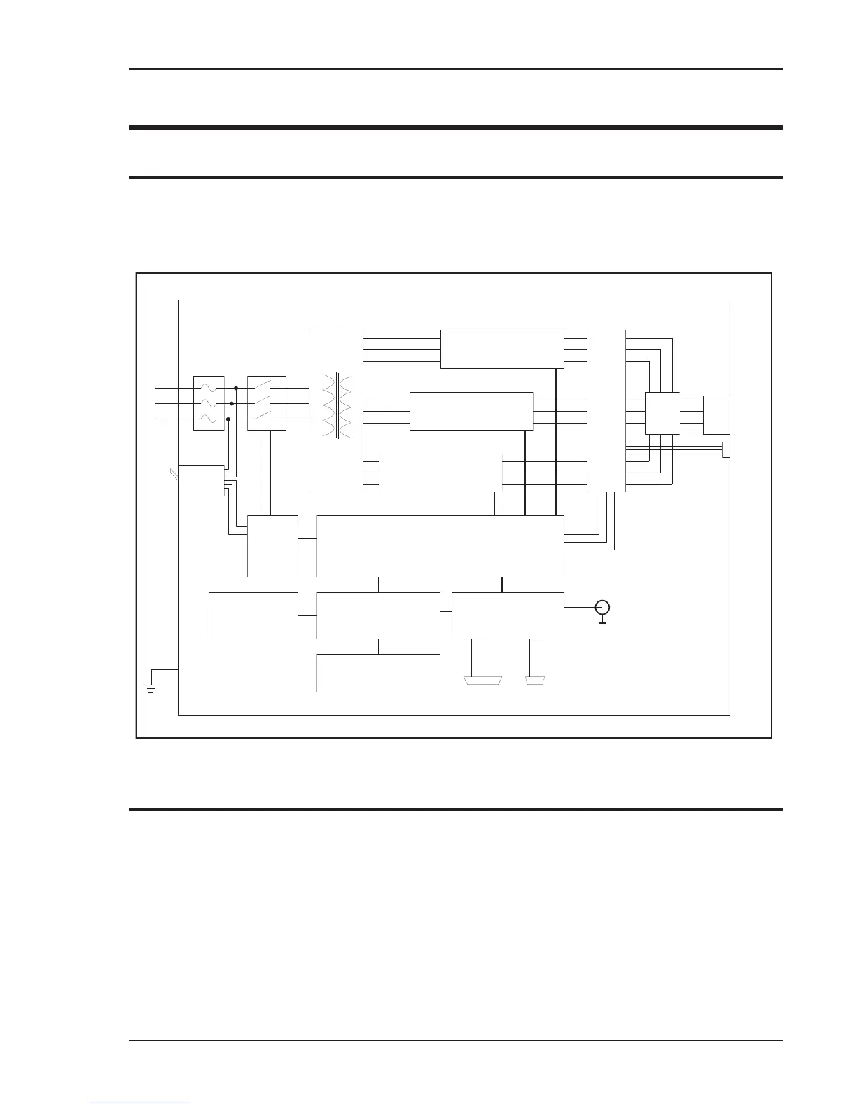
An explanation of the circuits in the MX Series is given in this section. Refer to Figure 5-1 for a
basic functional block diagram of the system. Figure 5-2 shows a more detailed system
interconnect for a MX-45-1 single-phase output unit. Other models have slightly different output
configurations.
POWER
MODULE A
POWER
MODULE B
POWER
MODULE C
Fuse
Block
Input
Transformer
AC
Input
Main
CB
System
Interface
Board
LV
Supply
Controller
CPU / Phase A
Controller
Phase B & C
Keyboard /
Display
Remote
Interface
IEEE-488 RS232C
K1/K2 Main
Contactor
& soft start
Curr ent
Voltage
Sense
Board
Range
Mode
Select
Output
Terminals
Ext I/O
Ext.
Sense
AC 3ø
A
B
C
N
Gnd
Figure 5-1: MX Series Functional Block Diagram
5.2 Overall Description
Three-phase input power is routed from the back of the cabinet to a fuse holder terminal block
located in the bottom front of the unit. The lower front access panel has to be removed to gain
access to the AC input connection fuse block. From the fuse block, the AC input is connected to
the three-phase input transformer primary. The input transformer provides the required isolation
between input and output of the MX and accommodates various input voltage ranges by
employing multiple taps. Three sets of three-phase output secondaries are provided by the
transformer to produce three 140 VAC unregulated output AC buses. Each of these outputs is
fed into one of the power modules. (A, B and C) The power modules can be individually removed
although for most configurations, all three are required. The power modules are located in the
middle of the MX chassis and can be pulled out from the front after removing the top access
panel and disconnecting the power input and output wiring.