User Manual – Rev AV AMETEK Programmable Power
MX Series 78
3.14 Output Filter Box Accessory
An optional output filter box (P/N 7003-424-1) is available which may be used reduce the amount
of ripple and noise present at the output of the MX30/45-3Pi.
The filter must be connected between the three-phase output of the MX30/45 and the unit under
test. To access the connection terminal blocks, the top cover of the filter case must be removed.
Note: Make sure all power is off when connecting the filter accessory.
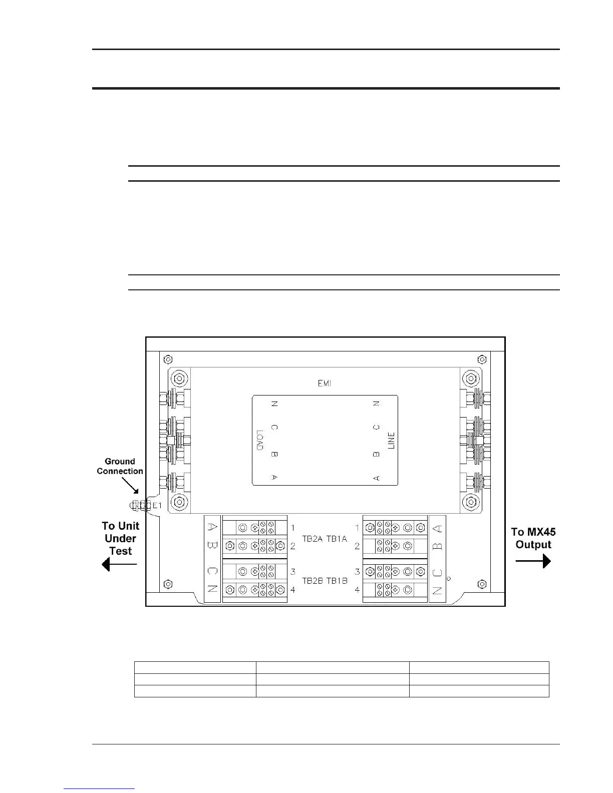
The output of the MX30/45 is connected to the input side of the filter. Use terminal blocks TB1A
(phases A and B) and TB1B (phase C and neutral) as indicated in Figure 3-21. The load can be
connected to the load side of the filter box using terminal blocks TB2A and TB2B. Do not swap
phases through the filter.
To compensate for voltage drop across the filter, the external sense connections can be made at
the load (load side of the filter).
Note: The filter box chassis must be connected to earth ground.
It is not recommended to use the ground connection on the MX30//45 itself for this purpose but
rather a ground point at the AC service to the MX30/45.
Figure 3-21: 7003-424-1 Output noise filter box.
Dimensions 7003-424-1:
12.125 “ x 16.125” x 4.125”