User Manual - Rev AV AMETEK Programmable Power
MX Series 169
Enter the actual DC load current for the CURR ZERO parameter
in the MEASUREMENT CALIBRATION screen and press the
ENTER key. Save this value by pressing the SET key.
DC Current Full-scale: Program the output to 0 volts on the 200 range. Apply load
resistor to the output. Refer to Table 6-1. Program 160 volts.
Enter the actual output current for the CURR FS parameter in
the MEASUREMENT CALIBRATION screen. Save this value
by pressing the SET key (Series I models only).
6.3.3 Three Phase Mode
As indicated earlier, for three-phase power systems, repeat the preceding steps for the Phase B
and C outputs. The order in which the outputs for each phase are calibrated is not important.
Press the PHASE key to select each output to be calibrated. Monitor the output of the respective
phase by moving the HI input of the Digital Multimeter and the current shunt as needed. The LO
input should remain connected to the common LO of the sense connector.
For the MX30-3Pi/MX45-3Pi operating in single-phase mode, it will be necessary to repeat the
current measurement calibration while the MX30-3Pi/MX45-3Pi is in the single-phase mode as it
maintains specific current measurement calibration coefficients for this mode. The load values
shown in Table 6-1 for MX30-1 and MX45-1 should be used on phase A only. The voltage
measurement calibration does not have to be repeated in single-phase mode as the same
coefficients for phase A are used in either phase mode.
6.3.4 Measurement Calibration Summary
The following Table is a summary of the preceding calibration steps. The value indicated by the
External DVM is called V
AC
or V
DC
. The current measured by the current shunt is called I
AC
or
I
DC
.
300 VAC Range, 240 VAC, 60 Hz, no load
150 VAC Range, 120 VAC, 60 Hz, full load
to 90% of max current range.
AC
DC Volt Zero
(
P/N 7003-400 only)
400 VDC Range, +2.0 VDC, no load
DC
400 VDC Range, + 320 VDC, no load
DC Current Zero
(
7003-400 only)
200 VDC Range, 160 VDC, 80 ohm load
DC
200 VDC Range, 160 VDC, full load to 90%
of max. current range.
DC
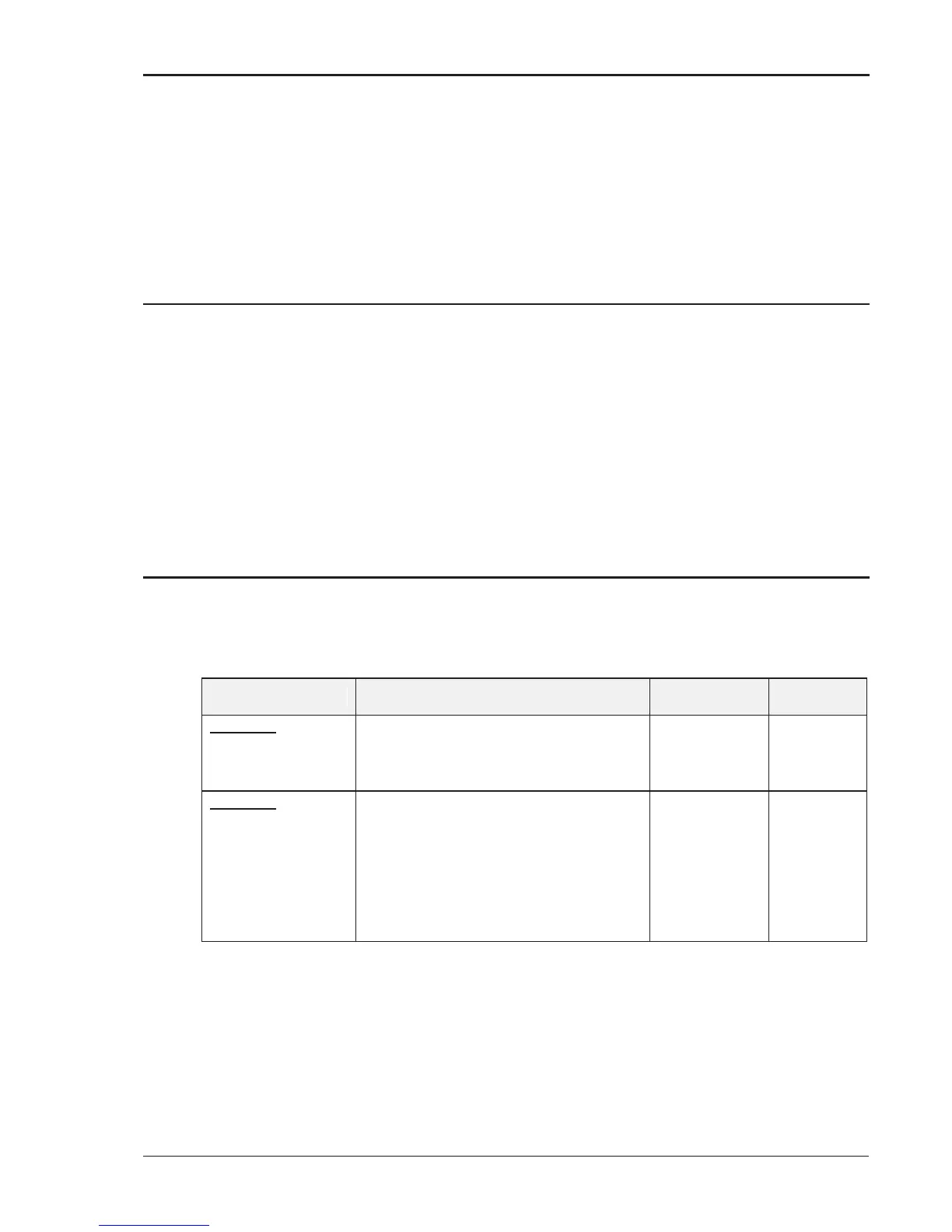
Table 6-2: Measurement Calibration Table
For a multi-phase power system, repeat Paragraph 6.3 for each phase. Move the external test
equipment to the phase that is being calibrated. Refer to Figure 6-2.
While viewing the calibration screen, press the PHASE key to select the respective phase.