User Manual - Rev AV AMETEK Programmable Power
MX Series 248
9.12 Option –EXTD: External Drive
The MX45 series power source system EXTD option can be used to drive the MX amplifier outputs with a
customer supplied external signal, apart from the standard drive signal from the programmable controller.
Using the EXTD allows a quick, low cost and simple way of direct real-time control of the output of the
power supply.
Each input is optically isolated from each other and the LV supplies inside the MX cabinet. If desired, the
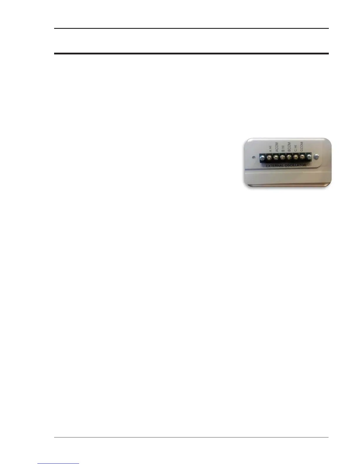
COM inputs for A, B and C can be tied together when a three-phase drive signal is used
External Oscillator connector
The input signal level is 0 – 7.00Vrms for FS output on 300V range
The input signal level is 0 – 7.00Vrms for FS output on 150V range
If voltage, current or frequency exceeds the system specifications the internal controller will automatically
take control and shut down the output and an error message will be generated. Short circuit and over
temperature protection is included during EXTD operation.
To enable the EXT drive option from the front panel controller, proceed as follows:
Go to MENU3
Go to UTILITY
Select VOLT/CURR CONTROL field
Now set ALC = OFF
Now toggle VOLT REF = EXT Use shuttle, or, +/- key to change field.
Once the MX is set to EXTD mode turn the output ON then apply the external signal. If the external signal
is applied prior to the output being turned ON, ringing can occur and the controller will shut down the
system. Ensure the EXTD is enabled and the output is ON prior to applying the external signal.
The MX EXTD circuit includes high frequency protection circuitry that results in a 100μsec delay from
Internal EXTD input the amplifier output.
Caution should be taken to minimize DC voltage when equipment under test includes a transformer. Any
DC voltage present on the external signal will be amplified, causing transformer saturation and automatic
shutdown of the MX Series.
The MX voltage slew rate is approximately 0.5V/μsec. External drive signal slew rates should be set to
similar speeds to avoid overshoot or ringing of the amplifier during voltage transient generation.
It’s recommended to discontinue use of the MXGUI while in EXTD mode of operation.