User Manual - Rev AV AMETEK Programmable Power
MX Series 182
check the connections and phase measurements if this is not the case to make sure the
measurement readings you get are indeed correct.
If it is necessary to adjust the pots, see Table 6-6 for the corresponding pot designators. The
top cover has to be removed to access these pots. They are located along the top edge of
the controller board(s). For Series I MX units, adjustments for phase A are on the phase A
board (7000-721), adjustments for phase B and C are on the phase B/C board (7000-722).
For Series II MX units, all adjustments are on the 7003-718 controller board. The reference
designators are the same on either series controller.
12. Repeat steps 2 through 11 for phase B and C. (except on single phase only models).
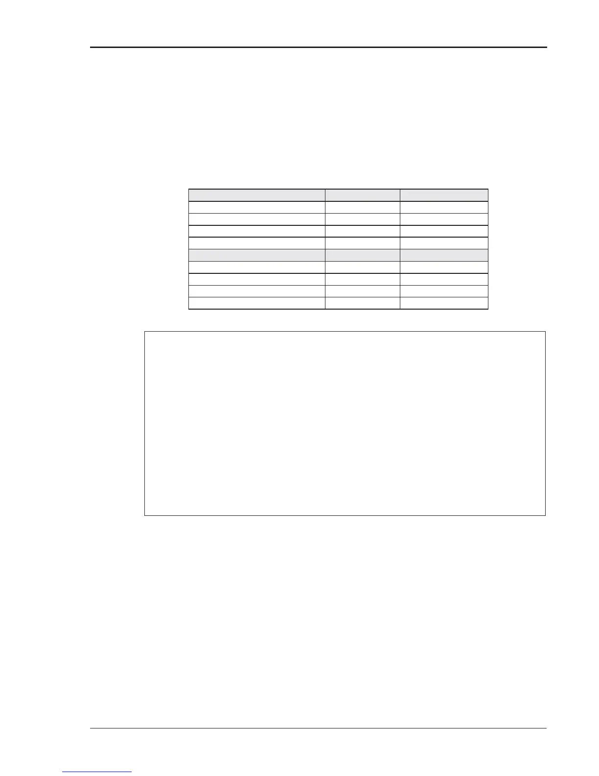
Phase A (7003-718-2 / -4)
Table 6-6: Programmable Z adjustment pots
NL
= Measured RMS voltage under no load.
L
= Measured RMS voltage under load
I = Measured RMS current.
F = Source frequency (50 Hz).
')= Phase angle shift between load and no load conditions. Record phase angle
from phase meter under NL and L condition and determine phase shift.
Formulas to calculate R and L component of output impedance:
NL
L
L
NL
L
Table 6-7: Formulas to calculate R and L