Photo 3.2.6
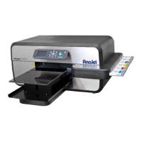
Once all the tubbing is in place we can now start connecting our dampers. Grab your damper assemblies
and start connecting them. Use the diagram above to make sure each tube is connected to the correct
damper. Once the elbow or the valve are connected to the damper you can not disconnect it anymore. If the
elbow or valve is disconnected the damper will be damaged and can no longer be used. Using a damaged
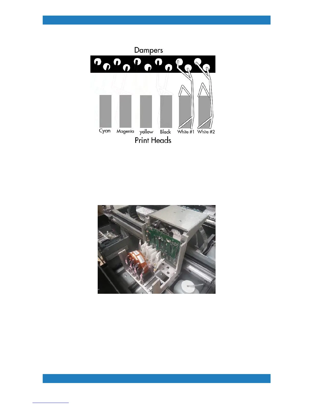
damper will result in poor ink flow and air will be introduced into the system. Photo 3.2.7
Photo 3.2.7
When all the dampers are connected we can now connect our Print and Purge lines to the dampers and
heads.
Connecting Print lines
We will start with the Print lines (set of 6). Split each tube up to the top of the carriage. Connect the first tube
to the first dampers. You will continue with the rest of the tubes until you reach #6. Its very important that the
correct tube goes to the correct dampers.Mixing your tubes can result in a improper fill of ink and printing
results will be poor. If there is extra tubing in the carriage you can cut a small amount if needed. Photo 3.2.8