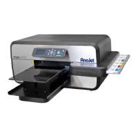
Photo 2.3-2 Photo 2.3-3
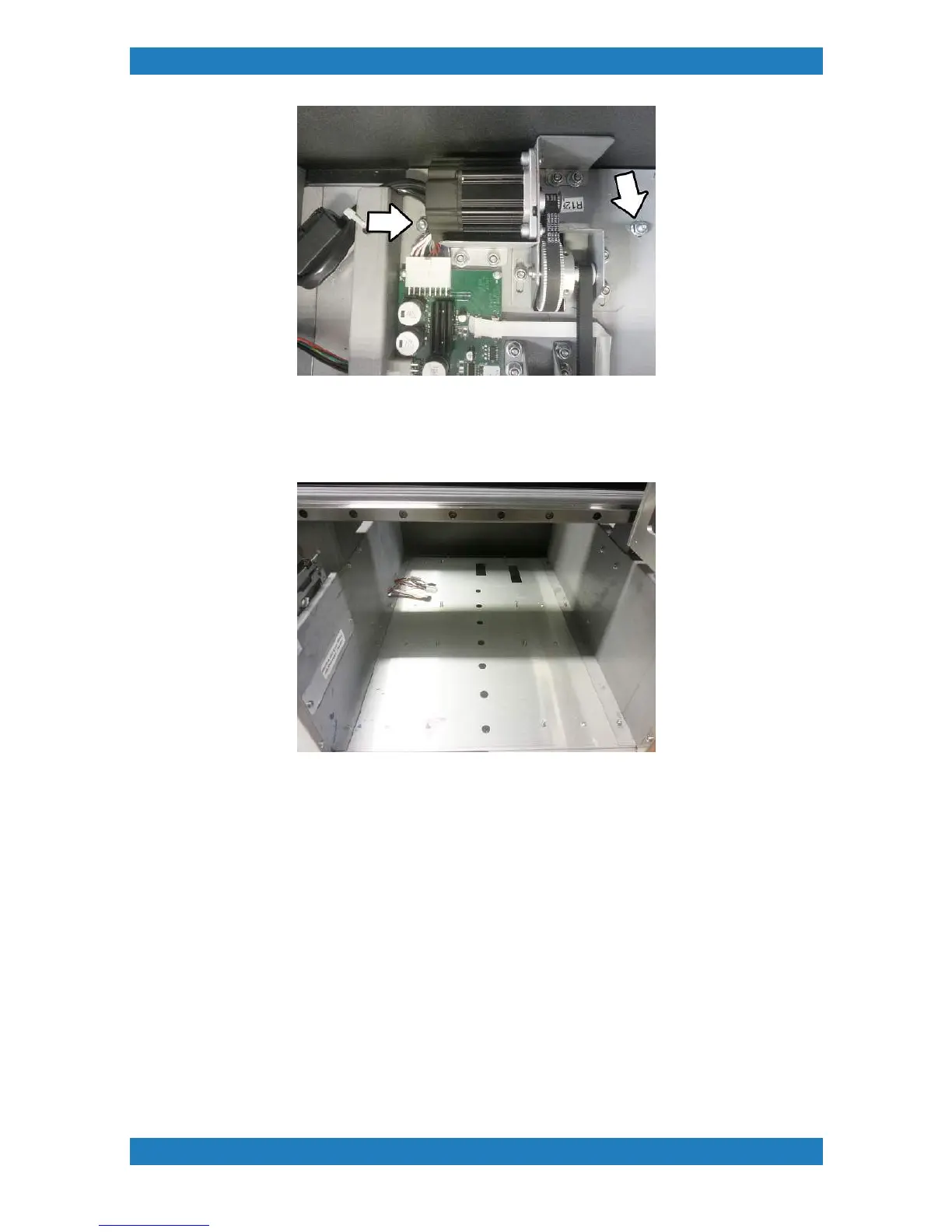
You will now be able to remove the entire table guide assembly. We recommended using 2 people to remove
the assembly from the printer and place it on a separate table. Your printer should now look like this see
Photo 2.3.4 below.
Photo 2.3.4
3. To adjust the tension on the Motor belt we must first loosen the Table Belt. Begin by removing the 3
Phillips screws located underneath the table assembly. See Photo 2.3.5. When the 3 Phillips screws are
removed you can now remove the front table cover.