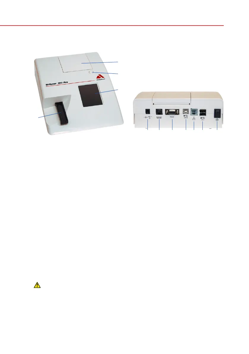
Component Function
1. Printer cover Flips up for insertion of printer paper
2. Printer cover button Push to open the printer cover
3. Display LCD touch screen for interfacing with the user
4. Test strip tray Holds the strip
5. Power inlet socket Socket used to connect the analyzer to the mains
adapter
6. PS2 socket For connecting a barcode reader or a keyboard
7. Serial interface For connecting a personal or host computer
8. USB B socket Socket used for serial-USB
9. Ethernet socket (Pro) Socket used to connect the analyzer to an Ethernet
network
10. USB A sockets Multifunctional socket used to connect USB devices
11. On/Off switch Powers the unit on. May be used to power the unit
off.
The standard power off procedure should be started
from the user interface.
Only connect the intended devices to the corresponding interface. If
you connect another device to the corresponding interface, the device
or the analyzer may be damaged e. g. because of wrong voltage. Be
sure to check all cables you are using to make sure they are opera-
tional. Verify the proper connection.
Front view Rear view
1
2
3
4
5 6 7 8 9 10 11
3.2 Components and Functions


 To Next Page