3. System description
3.1 Measuring principle
The test strip is moved below a fixed measurement unit on a slide called test strip
tray with an embedded reference pad. The analyzer reads the reference pad, fol-
lowed by each of the test pads on the strip.
The optical unit contains four LEDs that emit light at various wavelengths. Read-
ing is done electro-optically, as follows:
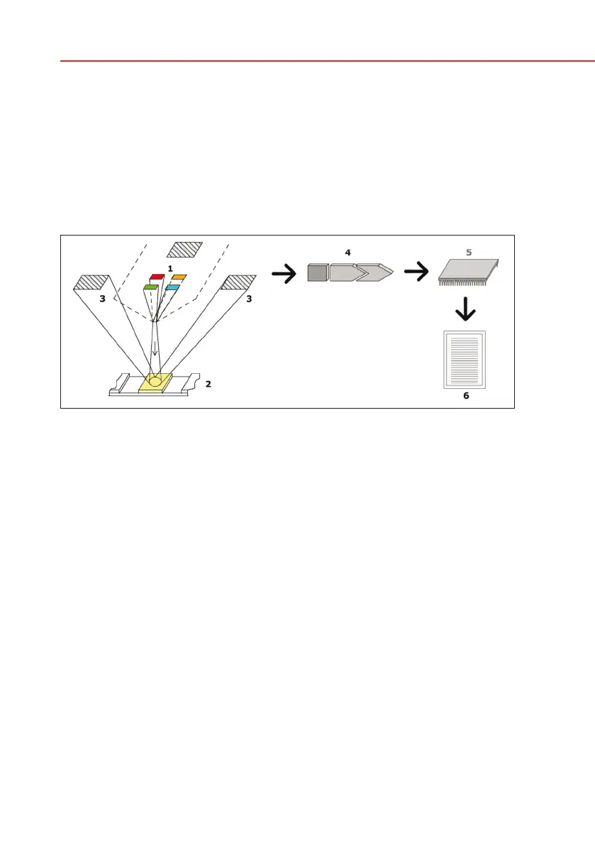
The LEDs (1) subsequently emit light of a defined wavelength onto the surface of
the test pad (2) from directly above the test zone. The light hitting the test zone is
reflected more or less intensely depending on the degree of color change of the
test pad (directly related to the concentration of the particular constituent in the
urine), and is picked up by the detectors, photodiodes (3) positioned at optimum
angles. The phototransistors send analogue electrical signal to an A/D converter
(4), which changes it to digital form. The microprocessor (5) then converts this
digital reading to a relative reflectance value by referring it to a calibration stand-
ard.
Finally, the system compares the reflectance value with the defined range limits
(reflectance values that are programmed into the analyzer for each parameter)
and outputs a semi-quantitative result (6).
Each test pad is read photometrically after a lead (incubation) time of about 55–
65 seconds.
Principle of measurement


 To Next Page