PAGE 13
Section 4 - Electrical ConnectionsSection 4 - Electrical Connections
Section 4 - Electrical ConnectionsSection 4 - Electrical Connections
Section 4 - Electrical Connections
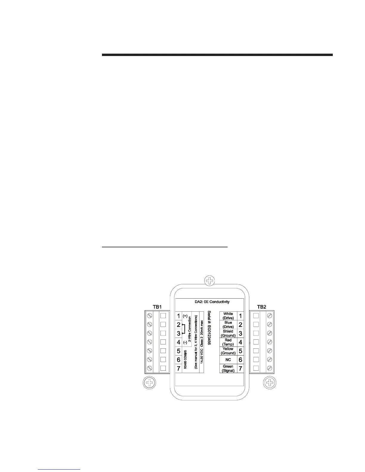
Figure 4-1 shows the terminal block arrangement and terminal designations for the transmitter.
NOTE: All terminals are suitable for single wires up to 14 AWG (2.5 mm2).
Wiring Tip! To comply with European Community (CE) electromagnetic
compatibility requirements, follow these general wiring guidelines:
1. Locate transmitter as far as possible from motors and other non-CE certified devices
with excessive electromagnetic emissions.
2. Use specified ferrites and cables. Failure to do so may eliminate compliance. Locate all
ferrites as close as possible to the transmitter.
• DC Power Supply Cable: Connect cable shield to earth ground at the supply end. Loop
cable 2-1/2 times through ferrite (Steward #28B0686-200, Fair-Rite Corp. #2643665702
or equivalent).
• Sensor Cable: Keep cable shields as short as possible. At the transmitter end, connect
the outer shield to earth ground, and the inner shield to the SHIELD terminal. Clamp
ferrite (Steward #28A2025-OAO, Fair-Rite Corp. #0431164281, or equiv-alent) on
sensor cable.
• Analog mA Output Cable (four-wire hookup only): Connect cable shield to earth ground
at the supply end. Loop cable 2-1/2 times through ferrite (Steward #28B0686-200, Fair-
Rite Corp. #2643665702, or equivalent).
FIGURE 4-1 Transmitter Terminal Designations