PAGE 4
Section 1 - General InformationSection 1 - General Information
Section 1 - General InformationSection 1 - General Information
Section 1 - General Information
1.1 Capability Highlights1.1 Capability Highlights
1.1 Capability Highlights1.1 Capability Highlights
1.1 Capability Highlights
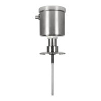
Sensor Input
The transmitter can be used with the Model HC1-Series electrodeless conductivity sensor.
These sensors have a built-in Pt 1000 RTD temperature compensator element.
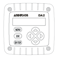
MEASURE Screen
The measure screen (normal display mode) can provide different readouts of measured data.
With the MEASURE screen displayed, press
ÕÕ
ÕÕ
Õ or
ÖÖ
ÖÖ
Ö to show:
• Measured conductivity, % concentration or TDS
• Measured temperature (°C or °F)
• Measured conductivity, % concentration or TDS and temperature
• Measured analog output value (mA)
• Uncompensated conductivity corresponding to concentration readout (only shown
when transmitter is set to measure concentration)
Password-Protected Access
For security, you can enable a passcode feature to restrict access to configuration and
calibration settings to authorized personnel only. See Section 7.5 for details.
Calibration Methods
Because each sensor has a unique zero point and span, always zero the sensor in air when
calibrating it for the first time (Section 8.2). Depending on the configured measurement
(conductivity, % concentration or TDS), different methods are available for calibrating sensor
span (see Section 8.3, 8.4 or 8.5 respectively). The analog output loop can also be calibrated
(Section 8.6).
Analog Output
The transmitter’s isolated 4-20 mA analog output can be assigned to represent one of these:
• Measured conductivity, % concentration or TDS
• Measured temperature.
Parameter values can be entered to define the endpoints at which the 4 mA and 20 mA analog
output values are desired (range expand). For analog output setup details, see Section 7.4.
NOTE: During calibration, the analog output is automatically held at the last measured value
and, upon completion, returned to its active state.
1.2 T1.2 T
1.2 T1.2 T
1.2 T
ransmitter Safetyransmitter Safety
ransmitter Safetyransmitter Safety
ransmitter Safety
The transmitter is completely safe to handle. Only low DC voltage is present.