PAGE 49
8.6 Analog Output Calibration8.6 Analog Output Calibration
8.6 Analog Output Calibration8.6 Analog Output Calibration
8.6 Analog Output Calibration
The transmitter analog output is factory-calibrated. However, it can be re-calibrated if desired.
NOTE: When the passcode feature is enabled (Section 7.5), you must successfully enter the
passcode before attempting to calibrate the analog output.
Also, the transmitter adjustment range for output values during calibration is ± 2 mA.
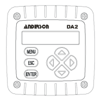
1. Press MENU key to display a “MAIN MENU” screen. If the
screen is not showing, use
ØØ
ØØ
Ø or
××
××
× key to display it.
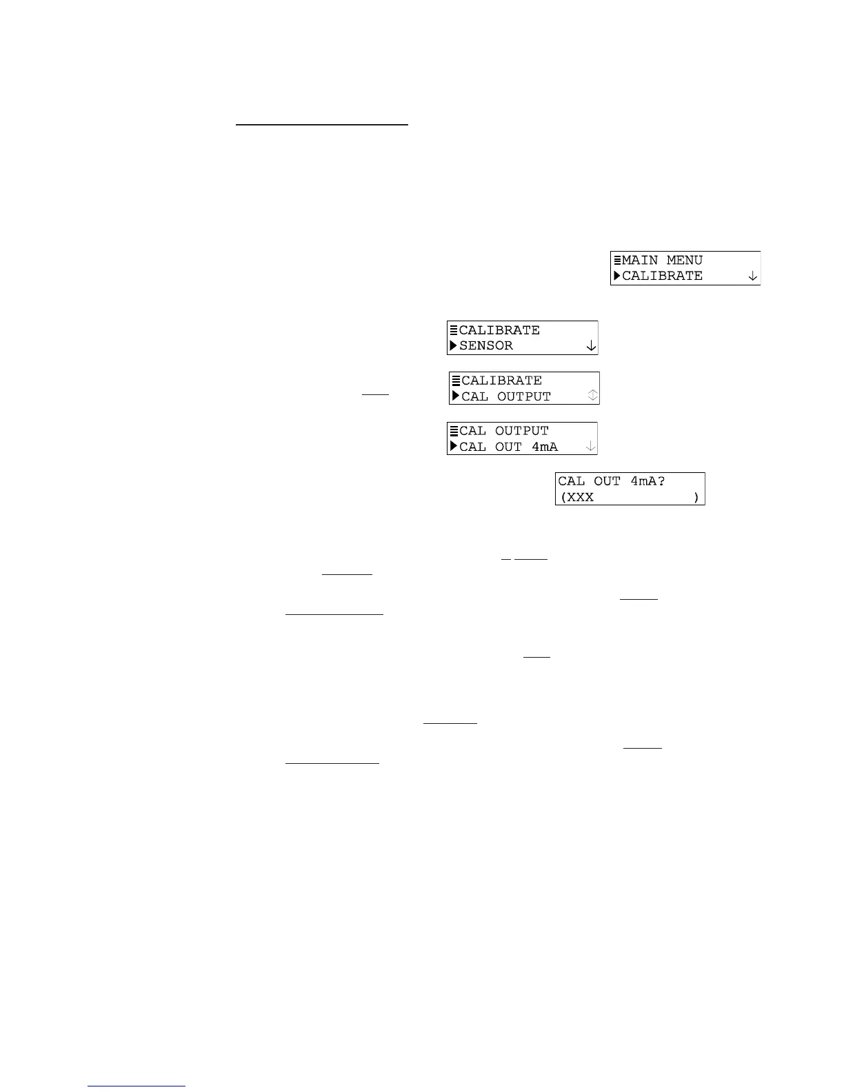
2. Press ENTER key to display
3. Press
ØØ
ØØ
Ø key once to display .
4. Press ENTER key to display
.
5. Press ENTER key again to display a screen like
. The
displayed value is “counts” — not mA — that dynamically change as the output is
adjusted.
6. Connect a calibrated digital multimeter
in series with the loop load to measure the
actual minimum mA output in the loop.
7. Use arrow keys to adjust the minimum output value to read exactly “4.00 mA” on the
digital multimeter — not the transmitter display, and press ENTER key to complete
calibration of the minimum endpoint value.
8. After the screen re-appears, press
ØØ
ØØ
Ø key once to display .
9. Press ENTER key to display a screen like . Once again the displayed value is “counts”
— not mA — that dynamically change as the output is adjusted.
10. Now measure the actual
maximum mA output in the loop with the digital multimeter.
11. Use arrow keys to adjust the maximum output value to read exactly “20.00 mA” on the
digital multimeter — not the transmitter display, and press ENTER key to complete
calibration of the maximum endpoint value.
This completes analog output calibration.