PAGE 14
4.1 HC1 Series Electrodeless Conductivity Sensor Wiring
Depending on how transmitter is mounted, route the sensor (or interconnect) cable into the
transmitter as follows:
• Wall/Pipe-mounted Transmitter: Route cable through left side cable entry knockout hole
in the back cover.
• Panel-mounted Transmitter: Route cable behind panel to the exposed TB2 terminal
strip.
• Integral Sensor-mounted Transmitter: Route cable through a 1/2” NPT female close
coupler and then through the swivel ball knockout hole and center hole in back cover.
(Do not open left side cable entry knockout hole in back cover.)
Wiring Tip! Route the sensor cable in 1/2-inch, grounded metal conduit to
protect it from moisture, electrical noise, and mechanical damage.
For installations where the distance between sensor and transmitter exceeds
the sensor cable length, indirectly connect the sensor to the transmitter using a
junction box and interconnect cable.
NOTE: Do not route the sensor cable in any conduit containing AC or DC power wiring
(“electrical noise” may interfere with the sensor signal). Also, always re-calibrate the
system when the cable length between sensor and transmitter changes.
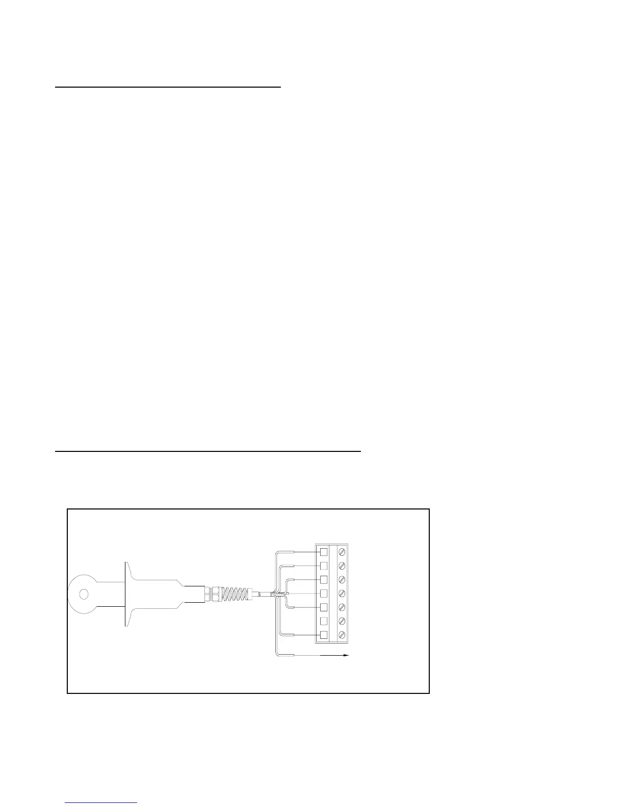
Refer to Figure 4-2 and connect the sensor (or interconnect) cable wires as shown, matching
colors as indicated. (Terminal 6 is unused.)
NOTE: For systems not requiring CE compliance and lacking an earth ground, connect the
outer shield to Terminal 3 on TB2.
FIGURE 4-2 Connecting HC1 Series Electrodless Conductivity Sensor
1 White (Drive)
2 Blue (Drive)
3 Shield (Ground)
4 Red (Temp)
5 Yellow (Ground)
6
7
Green
(Signal)
Green
Yellow
Inner Shield
White
Blue
Red
Outer Shield
To Earth Ground