PAGE 17
4.4 Four4.4 Four
4.4 Four4.4 Four
4.4 Four
--
--
-
Wire HookupWire Hookup
Wire HookupWire Hookup
Wire Hookup
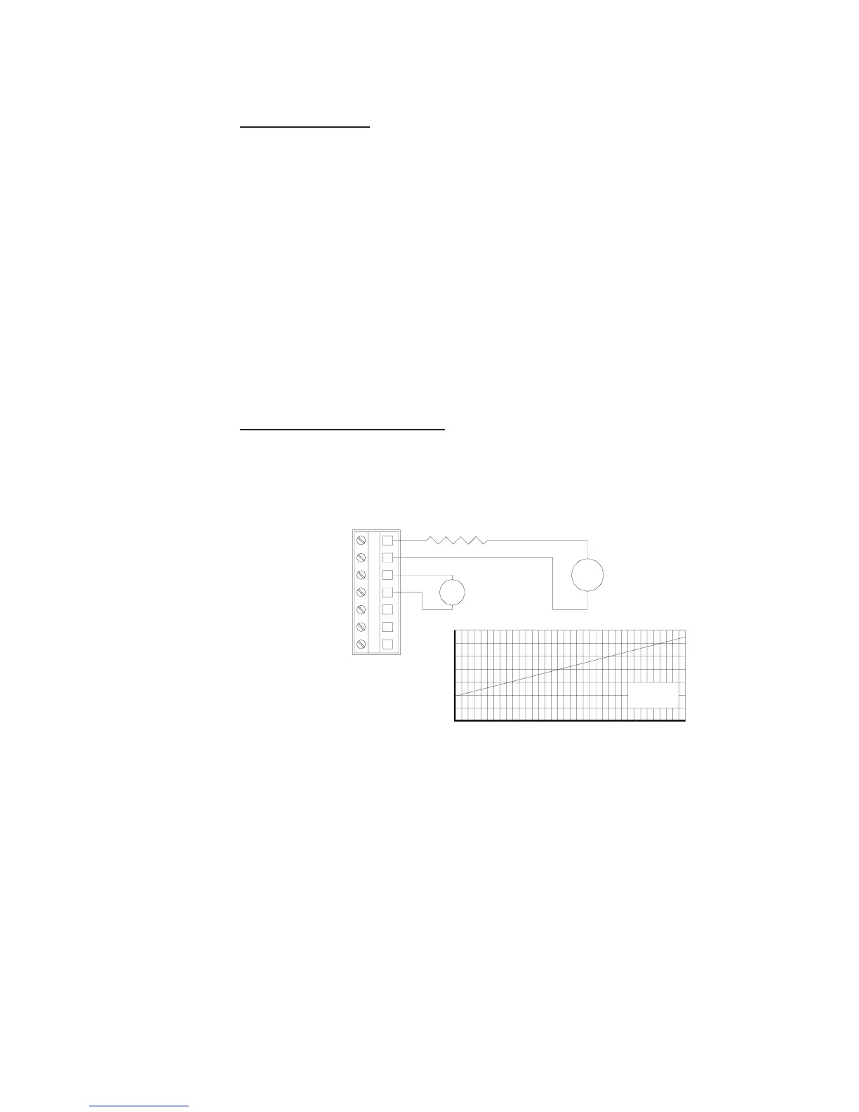
In a four-wire hookup, at least 12 VDC is required for operation.
Depending on how the transmitter is mounted, route the DC power, analog output wiring into the
transmitter as follows:
• Wall/Pipe-mounted Transmitter: Route cable through right side cable entry knockout
hole in the back cover.
• Panel-mounted Transmitter: Route cable behind panel to the exposed TB1 terminal
strip.
• Integral Sensor-mounted Transmitter: Route cable through right side cable entry
knockout hole in the back cover. (Do not open left side cable entry knockout hole in
cover).
Wiring Tip! Use high quality, shielded instrumentation cable
FIGURE 4-6 Four-Wire Hookup
5
7
6
1
3
4
2
-
Loop Resistance
(See nomograph)
+
-
+
1000
RESISTANCE
IN OHMS
161412
400
200
0
800
600
1400
1200
LOOP LOAD
50 Ohms/Volt
2624222018
DC VOLTAGE
3028
Loop Power
12-30VDC
Class 2
External Power
12-30VDC
Class 2