5-4 ISDB-T and BER Verification, Options 30 and 79 Option Verification
5-10 PN: 10580-00255 Rev. J MT8212E and MT8213E MM
Level Accuracy Verification
The tests in this section verify the level accuracy of the MT821xE in ISDB-T Signal Analyzer mode.
Setup
Procedure
1. Perform Zero/Cal on Sensor A and Sensor B of the power meter. Set the calibration factor of both sensors
to 473 MHz.
2. Confirm that the Power Amplifier is off.
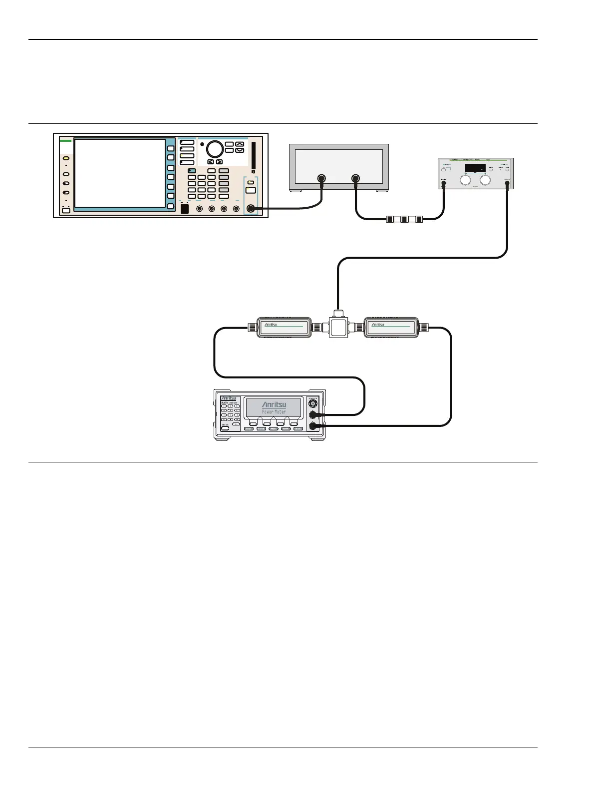
3. Connect the MG3700A Signal Generator, Power Amplifier with N(f)-BNC(m) adapters, RF Limiter,
MN63A Programmable Attenuator, Power Divider, Power Meter, and Power Sensors as shown in
Figure 5-2.
4. Preset the MG3700A.
5. Load the “ISDB-T_1layer_1ch” pattern on the MG3700A. Refer to “Frequency Accuracy Verification”
on page 5-7 if needing help on loading patterns.
6. Set the MG3700A frequency to 473.14285714 MHz.
7. Set the MG3700A level to –25 dBm.
8. Confirm that the Modulation On/Off key and the Output key both have LEDs On.
9. Turn On the power amplifier and allow it to warm up for at least 5 minutes.
10. Adjust the MN63A attenuator so that the Sensor A reading is –10 dBm ± 1 dB. Record the attenuation
reading in the AT(–10) column of Table A-22, “Level Accuracy Verification, AT(–10)” on page A-16.
Figure 5-2. ISDB-T Level Accuracy and 1 dB Compression Level Pre-test Setup
Function
Ethernet
Control Input
Modulation Input
Cursor/Edit
RF Output
3
MG3700
Vector Signal
Generator
250kHz-6GHz
3
ML2438A Power Meter
MA2482D
Sensor A
MA2482D
Sensor B
1870A
Power Splitter
A
B
MG3700A
RF Power Amplifier
MN63A
44-10
1N50C

 Loading...


