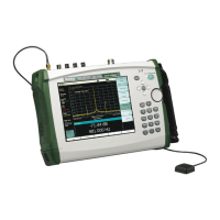
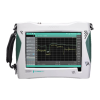
5-13 T1/T3 Analyzer Verification, Option 53 Option Verification
5-68 PN: 10580-00255 Rev. J MT8212E and MT8213E MM
T3 Transmit Level Test Verification
The tests in this section verify the transmit level of the T3 signal from the MT8221B in T1/T3 Analyzer mode.
Procedure
1. Preset the MT821xE. Press the Configuration main menu key, highlight Test Mode, and press the DS3
soft key.
2. Confirm that Tx LBO is set to Low.
3. Press the Pattern/Loop main menu key and then select the All Ones pattern.
4. Connect the PP090 75 ohm adapter to the oscilloscope Channel 1 input.
5. Install a 75 ohm BNC-BNC cable between the T3 Tx output and the 75 ohm adapter on the oscilloscope.
6. On the oscilloscope, press the blue Auto Setup button. Confirm that the Touch Screen button is activated.
7. View the Channel 1 peak-to-peak voltage and record it the LOW row of Table A-63, “Option 53,
T3 Transmitted Level Voltage” on page A-42. (Horizontal instability of the signal is normal.)
8. On the MT821xE, change the Tx LBO setting to DSX.
9. Record the “DSX” Measured Voltage (peak-to-peak) in the DSX row of Table A-63.
10. Press the Measurements main menu key and press Rx Signal.
11. Disconnect the BNC cable from the oscilloscope and use the cable to connect the T3 Tx and Rx connectors
together.
12. Press the Start/Stop main menu key to turn the measurement On (“Measure ON” appears in the
lower-left corner of the display).
13. Record the Vpp measurement that is shown on the MT821xE display in the DSX row of Table A-64,
“Option 53, T3 Transmitted Level Vpp Reading” on page A-42.
14. Change the Tx LBO (press the Configuration main menu key) to Low.
15. Press the Measurements main menu key, view the Vpp value, and record in the LOW row of Table A-64.

 Loading...


