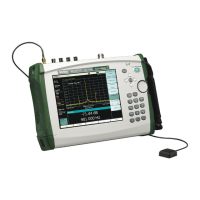
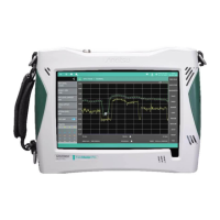
MT8212E and MT8213E MM PN: 10580-00255 Rev. J 8-1
Chapter 8 — Troubleshooting
8-1 Introduction
This chapter describes the primary troubleshooting operations that can be performed by all Anritsu Service
Centers. Perform the troubleshooting suggestions in the order they are listed. Operators of the MT821xE
should refer to the User Guide for troubleshooting help.
Only qualified Anritsu personnel should replace internal assemblies. Major subassemblies shown in Table 1-5,
“List of Replaceable Parts” on page 1-6 are typically the items that may be replaced. Because they are highly
fragile, items that must be soldered may not be replaced without special training. Removal of RF shields from
PC boards or adjustment of screws on or near the shields will detune sensitive RF circuits and will result in
degraded instrument performance.
8-2 Turn-on Problems
Instrument cannot boot-up, no activity occurs when the On/Off key is pressed:
1. Battery may be fully discharged. Confirm the battery is installed into the instrument and connect the AC
to DC converter (Anritsu part number 40-187-R) to the instrument allowing the battery to charge.
2. Battery may be the wrong type. Use only Anritsu approved battery packs. Some non-approved battery
packs will fit into the MT821xE, but are electrically incompatible and will not charge correctly.
3. External power supply may have failed or be the wrong type. Replace the external power supply.
4. On/Off switch is damaged. Replace the keypad PCB or rubber keypad.
5. Main PCB has failed. Replace the Main PCB/Spectrum Analyzer assembly.
Instrument begins the boot process, but does not complete boot-up:
1. Using Master Software Tools, perform the Emergency Repair procedure, then update the system software
(via the Tools menu).
2. During the boot-up process, the instrument stops with the message:
Failed to load touch screen calibration data. Please reboot the instrument.
a. Power the instrument off and boot up in boot strap mode (hold down the Shift - 4 - 0 keys while
pressing the power on button).
b. In boot strap mode, the instrument prompts you to perform a touch screen calibration. Follow the
on-screen directions until the touch screen calibration is complete, and then power cycle the
instrument.
c. Once the instrument boots up, ensure the firmware version is 1.30 or greater. If not, load the
latest firmware and perform a touch screen calibration.
3. The Main PCB has failed. Replace the Main PCB/Spectrum Analyzer assembly.
Instrument makes normal boot-up sounds, but the display has a problem:
1. If the display is dim, check the brightness setting under the System Menu / System Options.
2. Replace the Backlight Driver PCB.
3. Replace the LCD assembly.
4. The Main PCB has failed. Replace the Main PCB/Spectrum Analyzer assembly.

 Loading...


