7-10 LCD Backlight PCB Removal and Replacement Assembly Replacement
7-10 PN: 10580-00255 Rev. J MT8212E and MT8213E MM
6. Disconnect the LCD backlight cable from the LCD backlight PCB.
7. Disconnect the LCD cable from the side of the LCD.
8. Carefully remove the LCD.
9. Reverse the above steps to install the replacement LCD.
7-10 LCD Backlight PCB Removal and Replacement
This procedure provides instructions for removing and replacing the Cell Master LCD backlight PCB.
1. Open the case as described in Section 7-2 “Opening the Cell Master Case”.
2. Remove the Main PCB assembly from the front panel as described in Section 7-3 “PCB Assembly
Replacement”.
3. Perform Step 1 through Step 4 of Section 7-9 “LCD Assembly Replacement”.
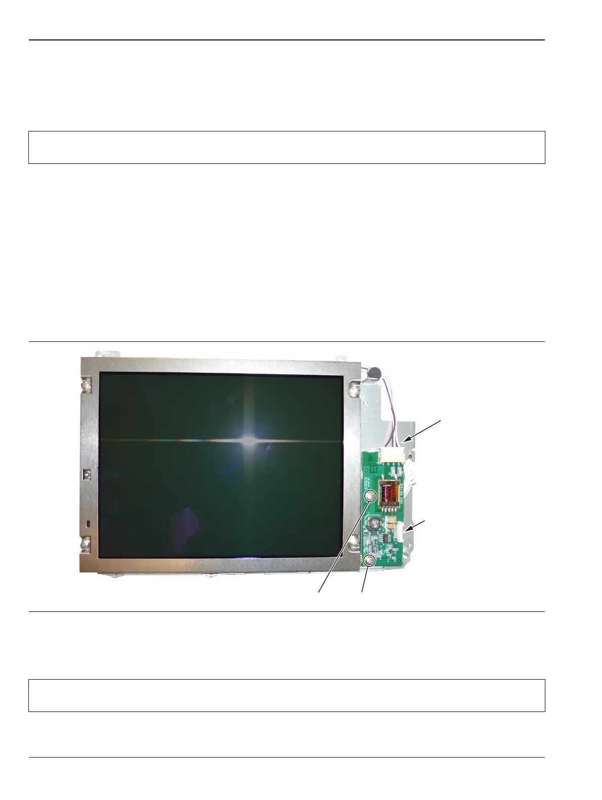
4. Disconnect the LCD backlight cable from the LCD backlight PCB.
5. Use a Phillips screw driver to remove the two screws securing the LCD backlight PCB to the Main PCB
assembly (Figure 7-13).
6. Carefully remove the LCD Backlight PCB.
7. Reverse the above steps to install the replacement LCD backlight PCB.
Note
Pay attention to the routing of the LCD Backlight Cable. The cable must be positioned so it is not
pinched when the instrument is reassembled.
Figure 7-13. Replacing the LCD PCB
Note
Pay attention to the routing of the LCD Backlight Cable. The cable must be positioned so it is not
pinched when the instrument is reassembled.
Remove 2 screws to replace LCD PCB
LCD Backlight
Cable
Ribbon Cable
Connects to
Keypad PCB

 Loading...


