8.2. Communicator LED Indicators
NOTE
Before you can verify operaon you must congure the Communicator.
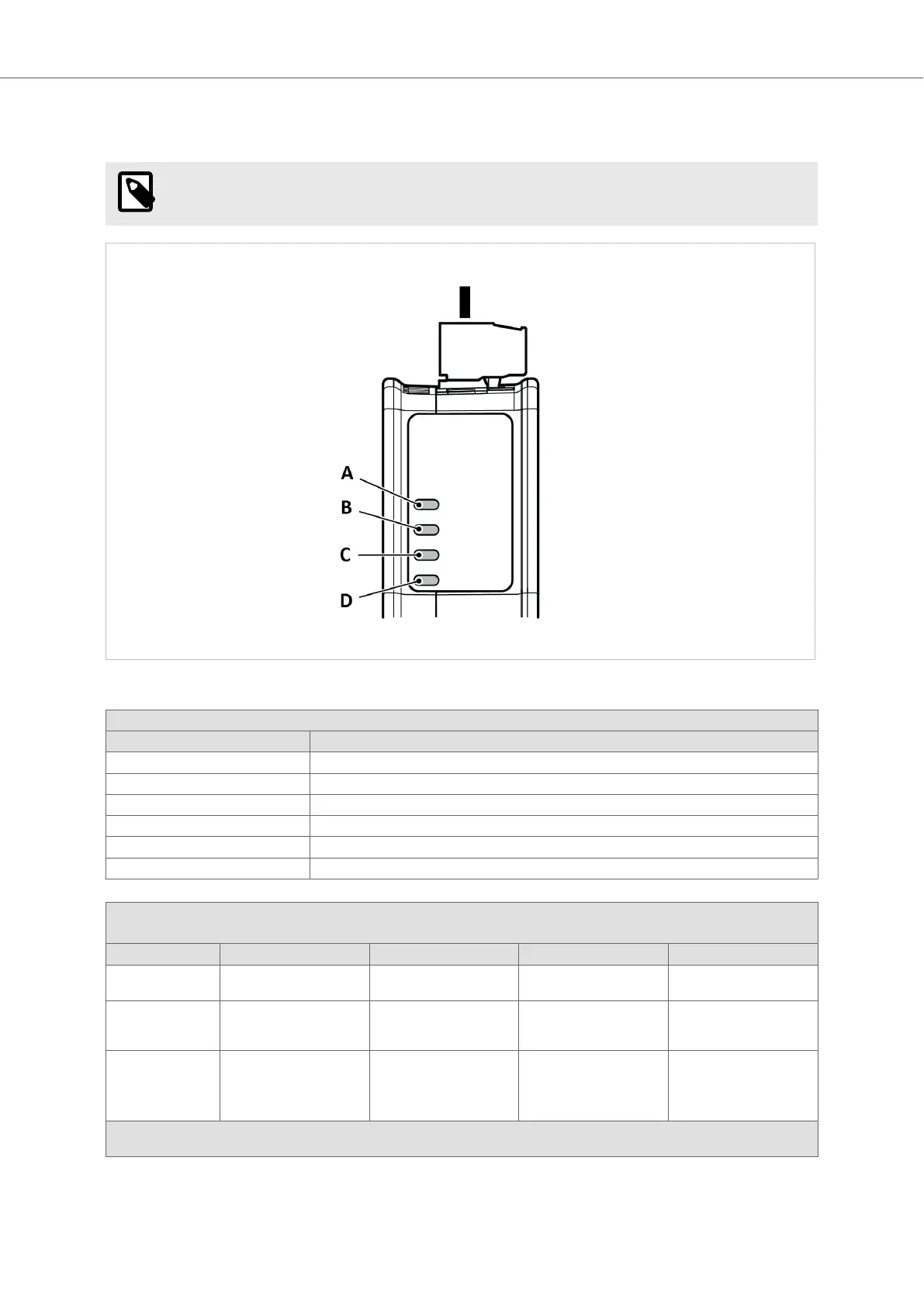
Figure 37. Gateway status (A), Lower connector (B), Upper connector (C) and (D) Security Switch
LED A - Gateway status
Operaon Status Descripon
O No power
Green, ashing Startup phase
Green, solid Operaonal
Red, solid Excepon/Fatal error
Red, ashing Invalid conguraon
Green/Red, ashing Power up self-test/Firmware update/Firmware recovery
LED B - PROFINET, Upper connector
LED C - EtherNet/IP, Lower connector
Operaon Status EtherCAT EtherNet/IP Modbus TCP PROFINET
O No power/EtherCAT device
in ‘INIT’-state
No power/No EtherNet/IP
IP address
No power/ No Modbus TCP
IP address
No power/No connecon
with IO controller
Green, ashing EtherCAT device in ‘PRE-
OPERATIONAL’-state
EtherNet/IP online, no
connecons established
Modbus TCP online, no
messages received
Used by engineering tools
to idenfy the node on the
network
Green, one ash EtherCAT device in ‘SAFE-
OPERATIONAL’-state
N/A N/A Connecon with IO
controller established
IO controller in STOP state
or IO data bad
*The EtherCAT RUN (green) and ERROR (red) LED behaviors are combined in LED (C)/(D). This can cause LED (C)/(D) to alternate between red and
green. The LED behavior sll represents the states described in the table above.
Communicator LED Indicators Anybus
®
Communicator
™
- PROFINET IO-Device to EtherNet/IP Adapter
SCM-1202-195 Version 1.0 Page 41 of 56