EasyManua.ls Logo

Anybus CompactCom 40 EtherNet/IP User Manual

Anybus CompactCom 40 EtherNet/IP
198 pages
To Next Page IconTo Next Page
To Previous Page IconTo Previous Page
Page #120 background imageLoading...
Page #120 background image
120
Doc.Id. HMSI-27-212
Anybus CompactCom 40 EtherNet/IP
Doc.Rev. 1.5
Command Details: Send
Category
Extended
Details
Command Code.: 17h
Valid for: Instance
Description
This command sends data on a connected socket. Message segmentation may be used to send up to 1472
bytes (see “Message Segmentation” on page 189).
NON-BLOCKING mode:
If there isn’t enough buffer space available in the send buffers, the module will respond with er-
ror code 0006h (EWOULDBLOCK)
BLOCKING mode:
If there isn’t enough buffer space available in the send buffers, the module will block until there
is.
Command Details
Note: To allow larger amount of data (i.e. >255 bytes) to be sent, the command data may be
segmented (see “Message Segmentation” on page 189).
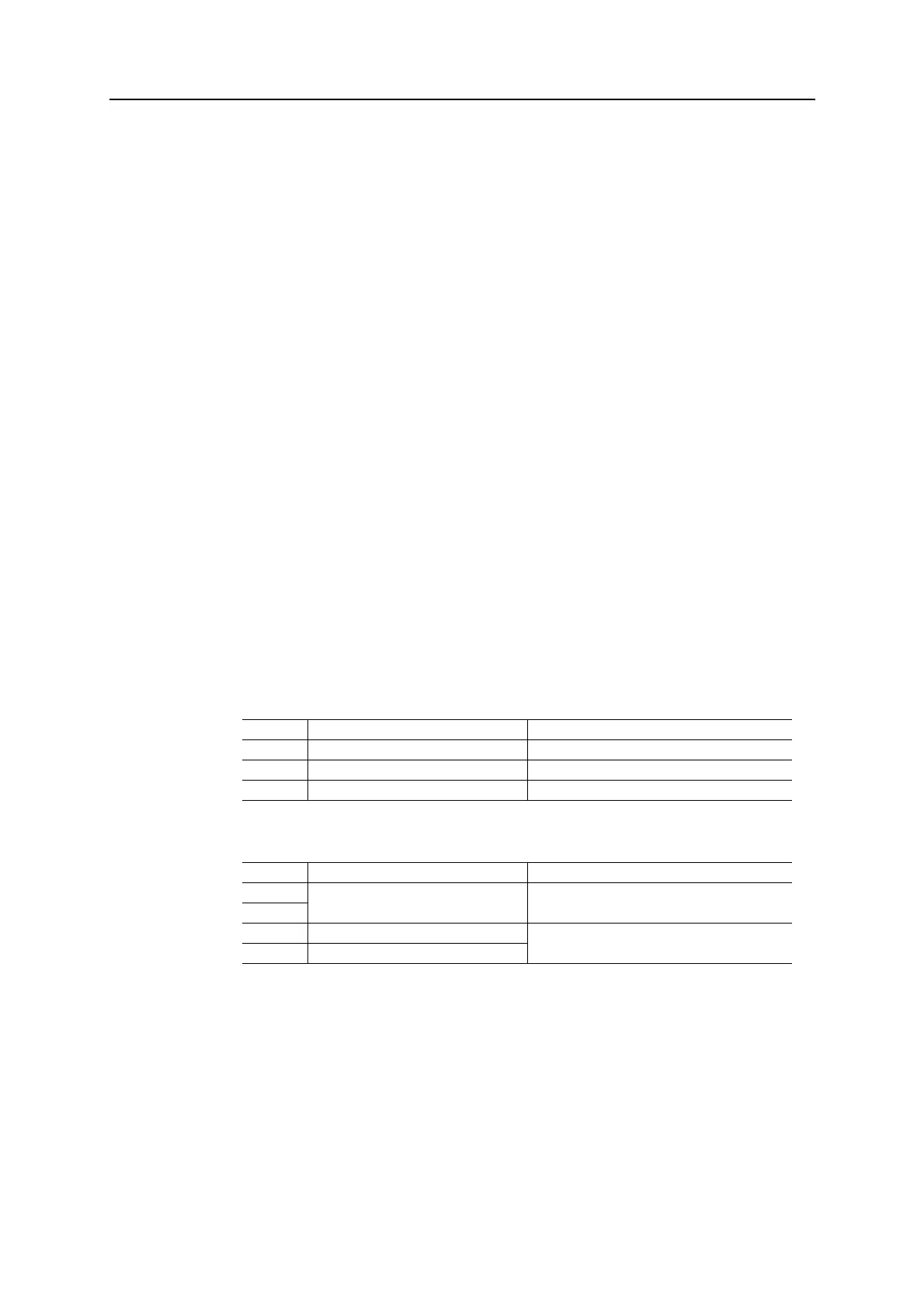
Response Details
Field Contents Notes
CmdExt[0] (reserved) (set to zero)
CmdExt[1] Segmentation Control see “Command Segmentation” on page 190
Data[0...n] Data to send -
Field Contents Notes
CmdExt[0] (reserved) (ignore)
CmdExt[1]
Data[0] Number of sent bytes (low) Only valid in the last segment
Data[1] Number of sent bytes (high)

Table of Contents

Question and Answer IconNeed help?

Do you have a question about the Anybus CompactCom 40 EtherNet/IP and is the answer not in the manual?

Anybus CompactCom 40 EtherNet/IP Specifications

General IconGeneral
Communication ProtocolEtherNet/IP
Form FactorCompact
ProtocolEthernet/IP
Data Rates10/100 Mbps
ConnectorRJ45
CertificationsCE, UL

Summary

Chapter 1 About the Anybus CompactCom 40 EtherNet/IP

1.2 Features

Lists the key features and functionalities offered by the module.

Chapter 2 Basic Operation

2.2 Device Customization

Details how to configure device identity, EDS files, and other settings.

2.3 Communication Settings

Explains TCP/IP and physical link settings for network communication.

2.4 Diagnostics

Describes how to access and interpret diagnostic information from the module.

2.5 Network Data Exchange

Covers application data, process data, and data type translation.

Chapter 4 Web Server

4.3 Server Configuration

Covers settings for the web server, including root directory and content types.

Chapter 6 Server Side Include (SSI)

6.3 Command Functions

Details various SSI command functions for interacting with the module.

Chapter 8 CIP Objects

8.3 Identity Object (01h)

Provides identification and general information about the module.

8.5 Assembly Object (04h)

Holds Process Data sent/received by the host application via static assemblies.

8.6 Connection Manager (06h)

Used for establishing and managing connections across subnets.

8.7 Parameter Object (0Fh)

Provides an interface to the module's configuration parameters.

8.12 ADI Object (A2h)

Maps instances in the Application Data Object to EtherNet/IP.

8.14 TCP/IP Interface Object (F5h)

Configures the TCP/IP network interface settings.

8.15 Ethernet Link Object (F6h)

Maintains link counters and status for IEEE 802.3 communications.

Chapter 9 Anybus Module Objects

9.5 Network Configuration Object (04h)

Holds network-specific configuration parameters settable by the end user.

Chapter 10 Host Application Objects

10.2 Functional Safety Host Object (E8h)

Specifies safety settings and is mandatory if Functional Safety is supported.

10.2 EtherNet/IP Host Object (F8h)

Implements EtherNet/IP specific features in the host application.

10.3 Ethernet Host Object (F9h)

Implements Ethernet features in the host application.

Related product manuals