EasyManua.ls Logo

Anybus CompactCom 40 EtherNet/IP User Manual

Anybus CompactCom 40 EtherNet/IP
198 pages
To Next Page IconTo Next Page
To Previous Page IconTo Previous Page
Page #193 background image
Doc.Id. HMSI-27-212
Anybus CompactCom 40 EtherNet/IP
Doc.Rev. 1.5
Appendix E
E. Technical Specification
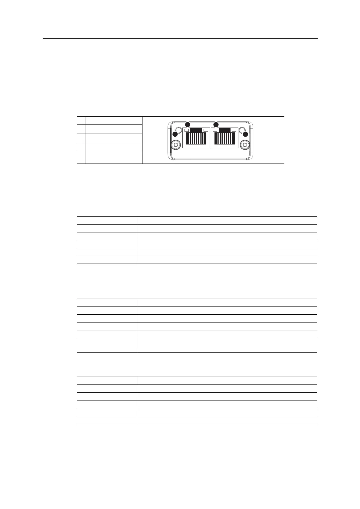
E.1 Front View
Ethernet Connector
Network Status LED
Note: A test sequence is performed on this LED during startup.
Module Status LED
Note: A test sequence is performed on this LED during startup.
LINK/Activity LED 3/4
Ethernet Interface
The Ethernet interface supports 10/100Mbit, full or half duplex operation.
#Item
1
Network Status LED
a
a. Test sequences are performed on the Network and Module Status LEDs during
startup
2
Module Status LED
a
3 Link/Activity LED (port 1)
4 Link/Activity LED (port 2)
LED State Description
Off No power or no IP address
Green Online, one or more connections established (CIP Class 1 or 3)
Green, flashing Online, no connections established
Red Duplicate IP address, FATAL error
Red, flashing One or more connections timed out (CIP Class 1 or 3)
LED State Description
Off No power
Green Controlled by a Scanner in Run state
Green, flashing Not configured, or Scanner in Idle state
Red Major fault (EXCEPTION-state, FATAL error etc.)
Red, flashing Recoverable fault(s). Module is configured, but stored parameters differ from currently
used parameters.
LED State Description
Off No link, no activity
Green Link (100 Mbit/s) established
Green, flickering Activity (100 Mbit/s)
Yellow Link (10 Mbit/s) established
Yellow, flickering Activity (10 Mbit/s)
1 2
3
4

Table of Contents

Question and Answer IconNeed help?

Do you have a question about the Anybus CompactCom 40 EtherNet/IP and is the answer not in the manual?

Anybus CompactCom 40 EtherNet/IP Specifications

General IconGeneral
Communication ProtocolEtherNet/IP
Form FactorCompact
ProtocolEthernet/IP
Data Rates10/100 Mbps
ConnectorRJ45
CertificationsCE, UL

Summary

Chapter 1 About the Anybus CompactCom 40 EtherNet/IP

1.2 Features

Lists the key features and functionalities offered by the module.

Chapter 2 Basic Operation

2.2 Device Customization

Details how to configure device identity, EDS files, and other settings.

2.3 Communication Settings

Explains TCP/IP and physical link settings for network communication.

2.4 Diagnostics

Describes how to access and interpret diagnostic information from the module.

2.5 Network Data Exchange

Covers application data, process data, and data type translation.

Chapter 4 Web Server

4.3 Server Configuration

Covers settings for the web server, including root directory and content types.

Chapter 6 Server Side Include (SSI)

6.3 Command Functions

Details various SSI command functions for interacting with the module.

Chapter 8 CIP Objects

8.3 Identity Object (01h)

Provides identification and general information about the module.

8.5 Assembly Object (04h)

Holds Process Data sent/received by the host application via static assemblies.

8.6 Connection Manager (06h)

Used for establishing and managing connections across subnets.

8.7 Parameter Object (0Fh)

Provides an interface to the module's configuration parameters.

8.12 ADI Object (A2h)

Maps instances in the Application Data Object to EtherNet/IP.

8.14 TCP/IP Interface Object (F5h)

Configures the TCP/IP network interface settings.

8.15 Ethernet Link Object (F6h)

Maintains link counters and status for IEEE 802.3 communications.

Chapter 9 Anybus Module Objects

9.5 Network Configuration Object (04h)

Holds network-specific configuration parameters settable by the end user.

Chapter 10 Host Application Objects

10.2 Functional Safety Host Object (E8h)

Specifies safety settings and is mandatory if Functional Safety is supported.

10.2 EtherNet/IP Host Object (F8h)

Implements EtherNet/IP specific features in the host application.

10.3 Ethernet Host Object (F9h)

Implements Ethernet features in the host application.

Related product manuals