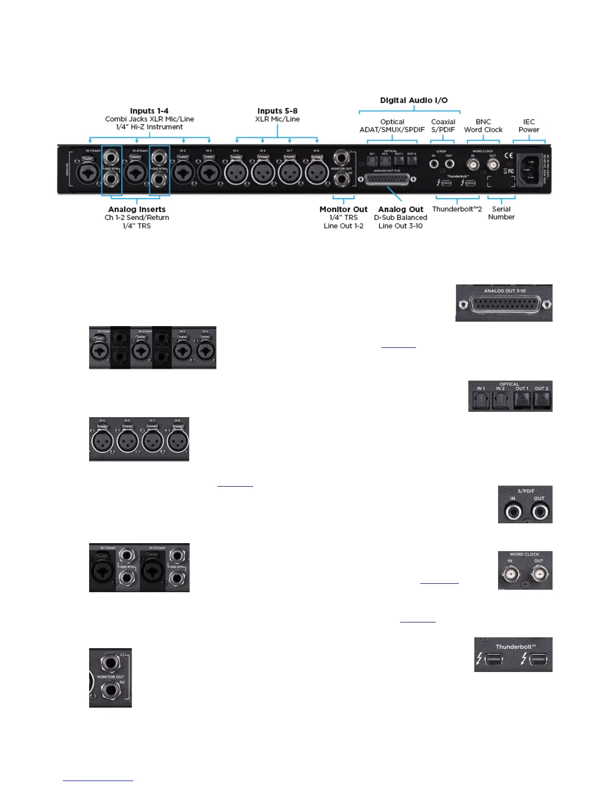
Rear Panel
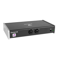
1. Inputs 1-4:
Combination (combi) jacks receive XLR or 1/4”
connectors
a. Use XLR for a microphone or line level input.
b. Use 1/4” for high-impedance (Hi-Z) instrument.
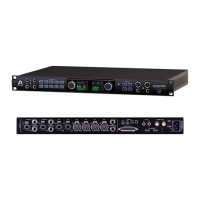
2. Inputs 5-8:
XLR for microphones or line level inputs.
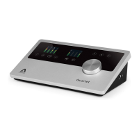
3. Analog Inserts: Channels 1 & 2 (page 28)
a. Send (top) - can use balanced TRS or
unbalanced TS 1/4” cables.
b. Return (bottom) - can use balanced TRS or
unbalanced TS 1/4” cables.
4. Monitor Out:
Balanced TRS outputs for connecting monitor
speakers.
5. Analog Out:
Balanced outputs 3-10.
Requires a 25-pin D-Sub
analog breakout cable.
6. Digital I/O: (page 30)
a. Optical (Toslink): Two In/Out Ports
i. ADAT, 8-channels per
port, 44.1-48k sample
rate.
ii. SMUX, 4-channels per port, 88.2-96k
sample rate.
iii. S/PDIF, 2-channels per port, 44.1-96k
sample rate.
b. Coaxial
i. Provides 2-channels of audio
at sample rates of 44.1 - 192k.
7. BNC Word Clock:
Used to transmit or receive word
clock signal between Ensemble and
other digital devices (page 37).
8. Thunderbolt 2: (page 10)
•
Two ports for daisy chaining
up to six devices.
•
It does not matter which
position Ensemble is placed
in the chain.
•
Backwards compatible with Thunderbolt 1 (see
Thunderbolt Notes on ).
8