System Control
ARM DDI 0363G Copyright © 2006-2011 ARM Limited. All rights reserved. 4-60
ID073015 Non-Confidential
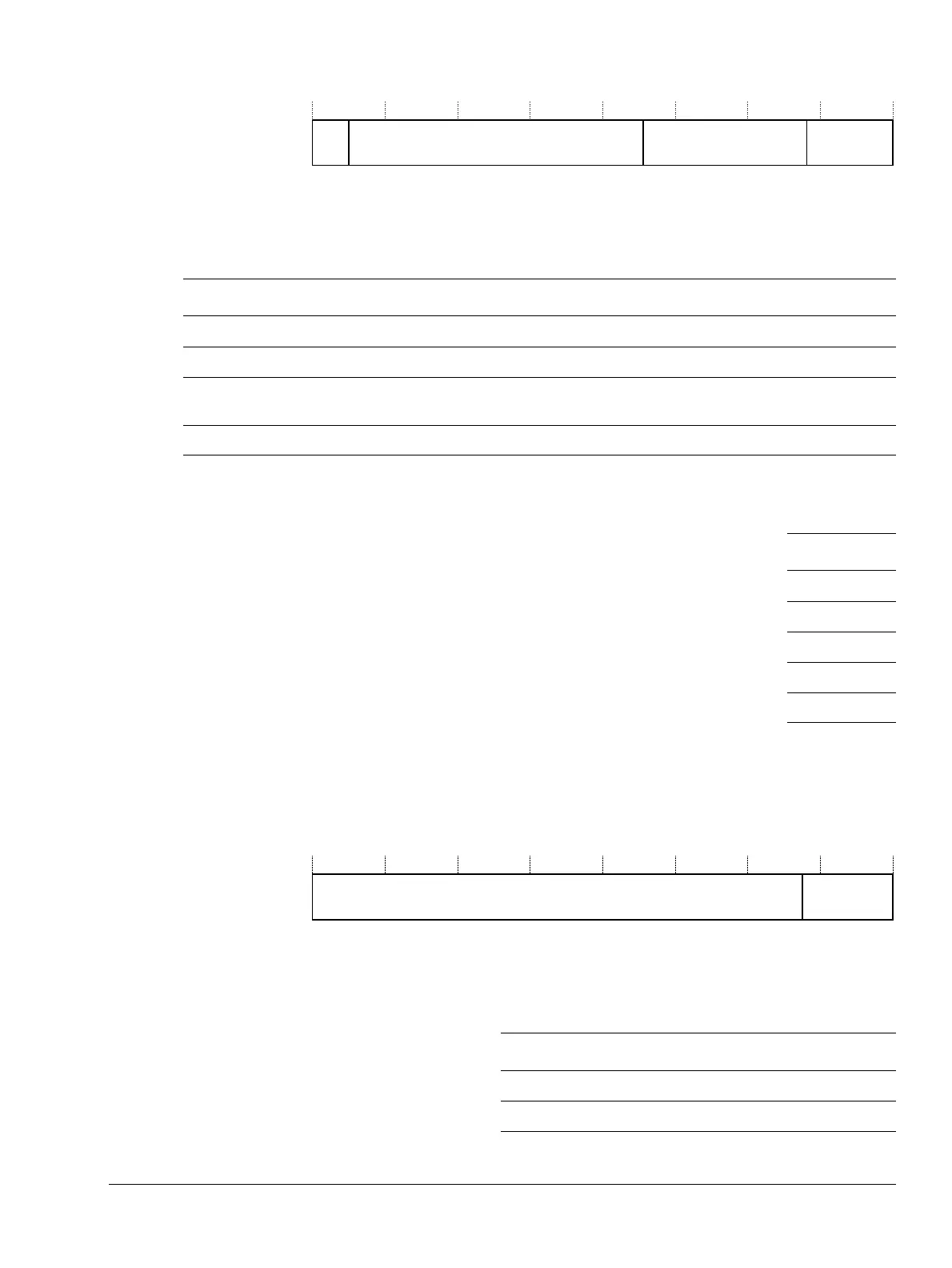
Figure 4-38 Set and Way bit assignments
Table 4-38 shows the Set and Way bit assignments.
Table 4-39 shows the Set and Way bit assignments.
See c0, Cache Type Register on page 4-15 for more information on cache sizes.
Address format
Figure 4-39 shows the invalidate and clean operations bit assignments.
Figure 4-39 Invalidate and clean operations bit assignments
Table 4-40 shows the invalidate and clean operations bit assignments.
Way
0
Set ReservedReserved
54S+4S+531 2930
Table 4-38 Set and Way bit assignments
Bits Name Function
[31:30] Way Indicates the cache way to invalidate or clean.
[29:S+5] - SBZ.
[S+4:5] Set Indicates the cache set to invalidate or clean. Because the cache sizes are configurable, the width
of the Set field is unique to the cache size. See Table 4-39.
[4:0]] - SBZ.
Table 4-39 Widths of the set field for L1 cache sizes
Size Set
4KB [9:5]
8KB [10:5]
16KB [11:5]
32KB [12:5]
64KB [13:5]
Table 4-40 Invalidate and clean operations bit assignments
Bits Name Function
[31:5] Address Specifies the address to invalidate or clean
[4:0] - SBZ