Debug
ARM DDI 0363G Copyright © 2006-2011 ARM Limited. All rights reserved. 12-20
ID073015 Non-Confidential
Table 12-12 shows the DBGWFAR bit assignments.
12.4.8 Vector Catch Register
The DBGVCR Register characteristics are:
Purpose Controls efficient exception vector catching.
Usage constraints • If one of the bits in this register is set and the instruction at the
corresponding vector is committed for execution, the processor
either enters debug state or takes a debug exception.
• Under this model, any prefetch from an exception vector can trigger
a vector catch, not only the ones because of exception entries. An
explicit branch to an exception vector might generate a vector catch
debug event.
• If any of the bits are set when the processor is in Monitor
debug-mode, then the processor ignores the setting and does not
generate a vector catch debug event. This prevents the processor
entering an unrecoverable state. The debugger must program these
bits to zero when Monitor debug-mode is selected and enabled to
ensure forward-compatibility.
Configurations Available in all processor configurations.
Attributes See Table 12-13 on page 12-21.
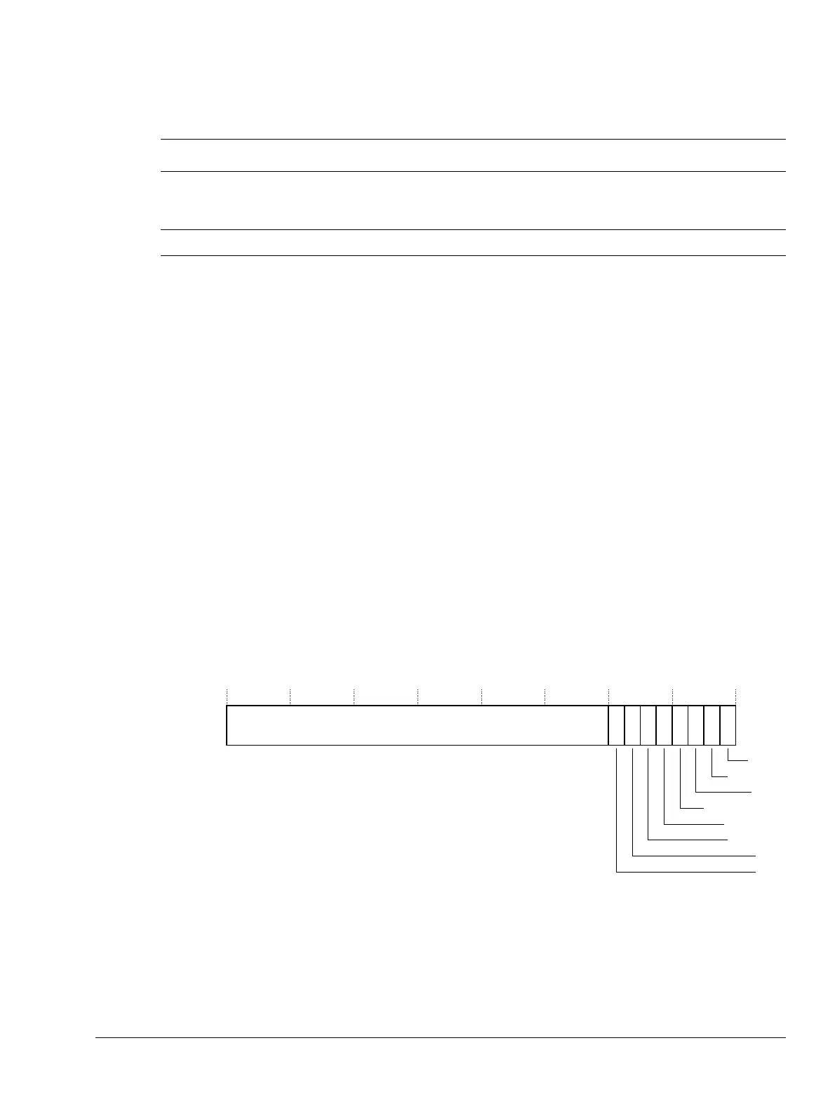
Figure 12-7 shows the DBGVCR bit assignments.
Figure 12-7 DBGVCR Register bit assignments
Table 12-12 DBGWFAR Register bit assignments
Bits Name Function
[31:1] Address This is the address of the watchpointed instruction. When a watchpoint occurs in ARM state, the
DBGWFAR contains the address of the instruction causing it plus an offset of
0x8
. When a
watchpoint occurs in Thumb state, the offset is plus
0x4
.
[0] - RAZ.
31 876543210
Reserved
Reset
Reserved
SVC
Prefetch abort
Data abort
Reserved
IRQ
FIQ