86
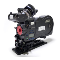
Motion Control Interface MCI-1
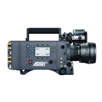
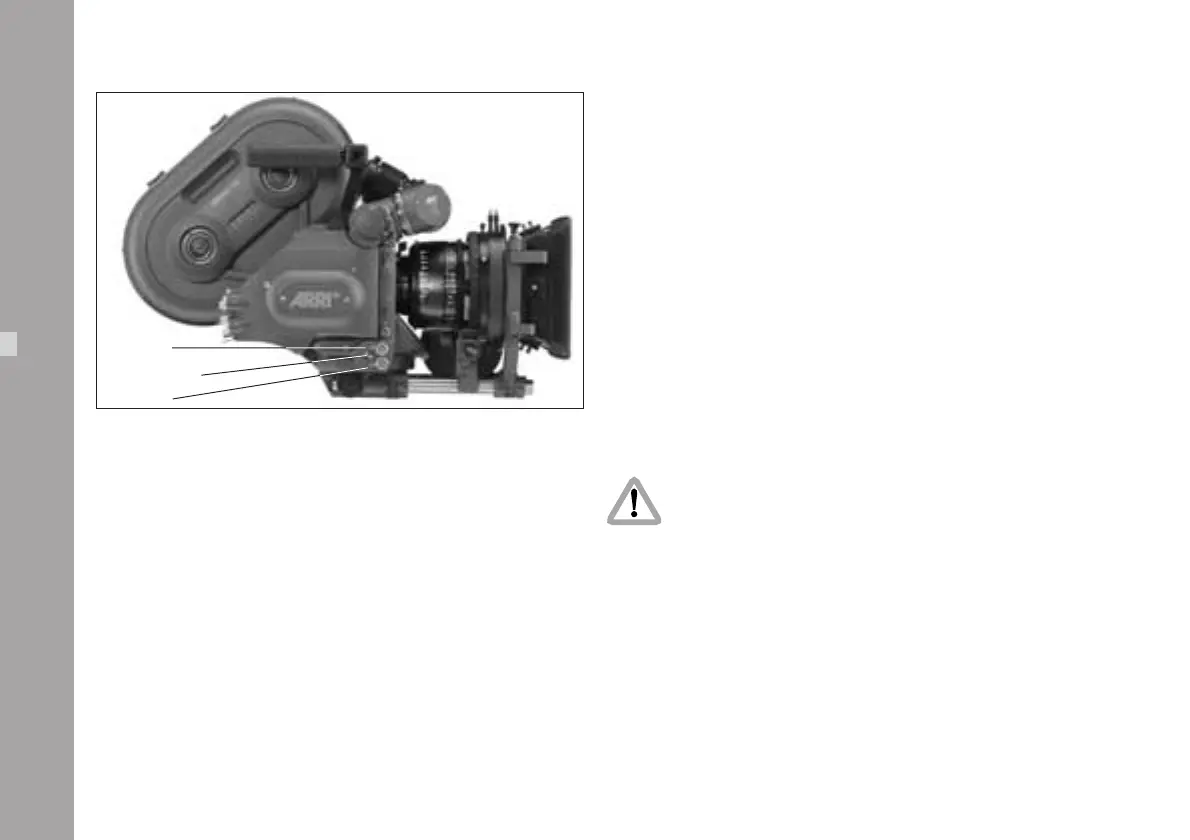
The MCI-1 ➪ photo is attached to the 26pin connector
on the lower right side of the camera and secured with a
screw ➪ photo to the handgrip mount (use a 3mm allen
key). It adds the motion control modes to the camera and
splits the 26pin connector in two differently coded 12pin
Fischer connectors for the capping shutter and the interface
for external motion control computer.
• The MC socket ➪ photo is for the motion control computer.
• The ICS socket ➪ photo is for the capping shutter.
The capping shutter has to be fitted with a 12pin Fischer
socket and the K-MCI-ICS K2.52147.0 has to be used.
ATENTION: switch off power and disconnect
battery cable before installing the MCI-1 and
attaching cables to the MC and ICS socket.
Accessories
fastening screw
MC-socket
ICS-socket
 Loading...