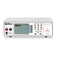
External Measuring Device
The 620L has an access panel on the back of the instrument that can be removed to
access the MD external PCB. The MD external PCB may be configured for a simple
resistive measuring device or a two pole measuring device similar to MD “E”. No
components are supplied for the population of the PCB.
Frequency Check
The Line Leakage test can be configured to verify the bandwidth of the leakage
current “voltmeter” by setting the Probe configuration to “Probe-HI to Probe-LO” and
selecting the medical device “Frequency Check”. The selection is intended for meter
verification purposes only and has no application for normal testing.
The calculation of the displayed leakage current will use 1000 for R in the
calculation of V/R=I where I is the leakage current displayed and V is voltage across
the measuring device (MD). When an external frequency generator is applied to the
probe inputs, the current display will be equal to Voltage generator/1000. The
readings can then be correlated to verify the voltmeter bandwidth.
Since the voltage is being applied directly across the MD voltmeter amplifier inputs, it
is not necessary to actually install a 1K resistor to the external MD input. It is
necessary to have the 0 resistors installed in position R1 and R3 on the external
measuring device PCB to operate in this mode. If the external Measuring Device has
been populated in a different configuration, it will be necessary to create a temporary
short on R1 and R3 to operate in this mode. Another option would be to acquire a
spare external measuring device PCB for the meter verification purpose.

 Loading...