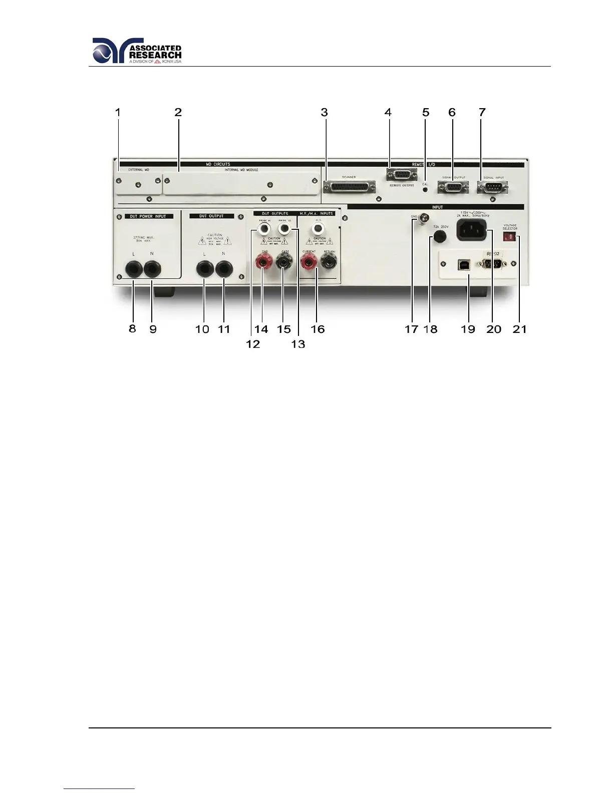
3.2.2. Rear Panel Controls
1. EXTERNAL MEASURING DEVICE: Contains an external Measuring Device
PCB that will enable during a Line Leakage test when “External” is selected
from the “Meas. Device” soft key. The external MD allows the operator to
configure a custom measuring device using either a simple resistive component
or a complex two pole network.
2. INTERNAL MD MODULE: Provides the operator access to the measuring
device that is currently selected.
3. SCANNER CONNECTOR: For connection of optional external 8 channel
Scanner. For more information refer to section 8. Options.
4. REMOTE OUTPUT: For connection of optional AC1000 power source. When
used to deliver DUT power, the AC1000 may be configured to work in a
master/slave mode with the 620L. For more information refer to section 8.
Options.
5. CALIBRATION BUTTON: To put the instrument into the calibration mode
push this button and turn on the power switch simultaneously.
6. REMOTE SIGNAL OUTPUT: 9-Pin D-type subminiature female connector for
monitoring PASS, FAIL, and PROCESSING output relay signals (See section
6. Connection of Remote I/O for more detailed information).