6. CONNECTION OF REMOTE I/O
Two 9-pin “D” type connectors mounted on the rear panel provide REMOTE-INPUT-
OUTPUT control and information. These connectors mate with a standard 9 pin D-
sub-miniature connector provided by the user. The output mates to a male (plug)
connector while the input mates to a female (receptacle) connector. For best
performance, a shielded cable should be used. To avoid ground loops the shield
should not be grounded at both ends of the cable. Suggested AMP part numbers for
interconnecting to the Remote I/O are shown below:
205204-4 PLUG SHELL WITH GROUND INDENTS
205203-3 RECEPTACLE SHELL
745254-7 CRIMP SNAP-IN PIN CONTACT (for plug)
745253-7 CRIMP SNAP-IN SOCKET CONTACT (for receptacle)
745171-1 SHIELDED CABLE CLAMP (for either plug or receptacle)
747784-3 JACKSCREW SET (2)
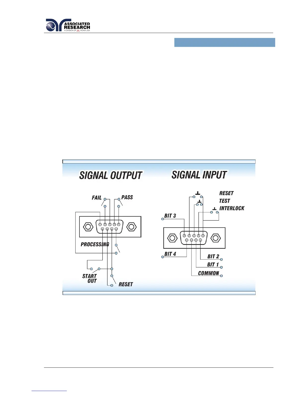
6.1. Remote Signal Outputs
The rear panel connector provides three output signals to remotely monitor PASS,
FAIL, and PROCESSING conditions. The monitoring signals are provided by three
normally open internal relays that toggle ON and OFF to indicate the condition of the
tester. These are normally open free contacts and will not provide any voltage or
current. The ratings of the contacts are 1 AAC / 125 VAC (0.5 ADC / 30 VDC). The
signal outputs are provided on the 9-pin female “D” type connector. Below is a list that
indicates what conditions activate each pin. When a terminal becomes active the
relay closes thereby allowing the external voltage to operate an external device.