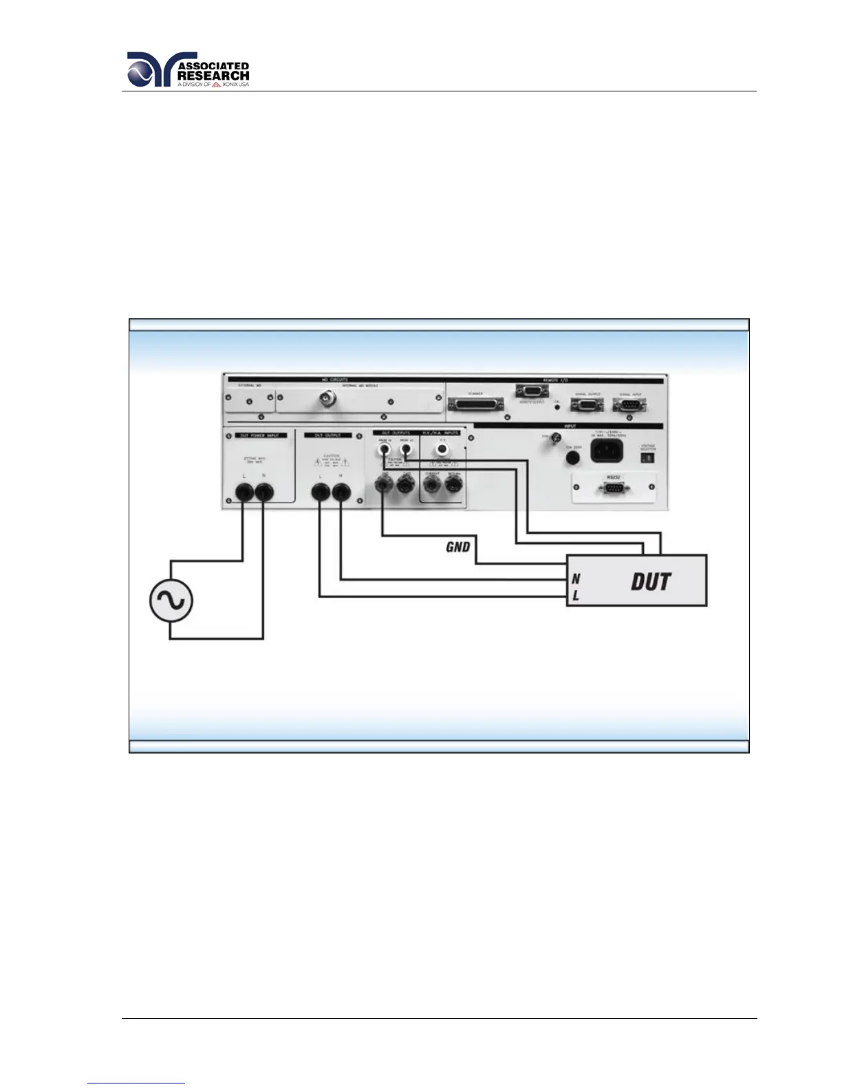
5.1.2. Connecting the Test Leads
Included with the instrument are two black cables, each terminated with an alligator
clip on one side. These cables are used to measure leakage current during either a
Line Leakage test or a Functional Run test. Connect one or more of these cables to
the Probe-HI and Probe-LO terminals on the rear panel of the 620L (the sense point is
determined by the Line Leakage test Probe Configuration parameter, see section
4.5.2. Line Leakage Test for more information). Connect the red test lead (also
terminated in an alligator clip) to the GND terminal on the rear panel of the 620L. This
will provide the return connection for all leakage current measurements. The alligator
clips may be used to provide a connection to the necessary points on your DUT.
5.1.3. DUT Output Connections
These connections provide power to the DUT during a Line Leakage or Functional
Run test. In order to access the DUT Output Connections, you must remove the
cover plate on the rear panel of the 620L. Once removed, the set of black 10 AWG
cables (included) may be used for the DUT Output connections for applications up to
and including 40 amps. These cables are terminated on one end and may be easily
connected to the DUT Output screw-mount terminals. The opposite ends of the
cables are left un-terminated so the operator may adjust the length and/or termination
method.