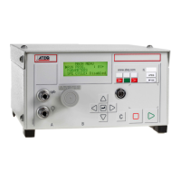
Chapter 5 - Accessories
UM-18400E-U ATEQ F580 User manual Page 148/168
2.3.2. 5) J5 I/O outputs connector (TOR)
1 2 3 4 5 6 7 8 9 10111213141516
60 V AC/DC maximum, 200 mA maximum VOLT FREE OUTPUTS
Pin Extended mode Standard mode Compact mode
1 COMMON negative COMMON negative COMMON negative
2 E1 Stop cycle (RESET) Stop cycle (RESET) Stop cycle (RESET)
3 E2 Start cycle (start) Start cycle (start) Start cycle (start)
4 E3 ATR request Select head 1 Select head 1
5 E4
Auto-diagnostics check
request
Select head 2 Select head 2
6 E5
Customer calibration
request
Select head 3 Select head 3
7 E6 Auto zero request Select Program 2 Select Program 2
8 E7 Manual / Automatic Select Program 3 Select Program 3
9 COMMON negative COMMON negative COMMON negative
10 E8 Select Program 2 Select Program 5 Select Program 5
11 E9 Select Program 3 Select Program 9 Select Program 9
12 E10 Select Program 5 Select Program 17 Select Program 17
13 E11 Select Program 9 Select Program 33 Select Program 33
14 E12 Select Program 17 ATR request ATR request
15 E13
Select Program 33
Check calibration request
Check calibration
request
16 E14 Not used Calibration request Calibration request
Note: in the case of the standard mode configuration, the simultaneous activation of
pins 14, 15 and 16 causes an auto-zero request in the units selected.