Manual, F/T Sensor, Data Acquisition (DAQ) Systems
Document #9620-05-DAQ.indd-20
Pinnacle Park • 1031 Goodworth Drive • Apex, NC 27539 • Tel: 919.772.0115 • Fax: 919.772.8259 • www.ati-ia.com • Email: info@ati-ia.com
28
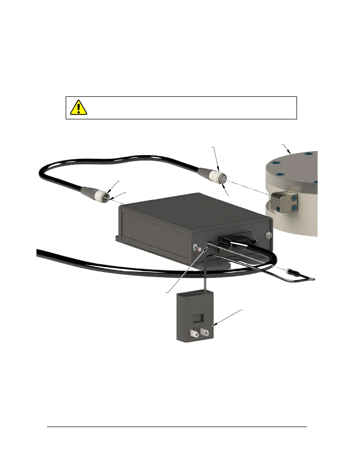
4. If equipped, plug 12 volt wall mount power supply into outlet and connect the power supply cable to the
PS or IFPS box.
5. For larger TIF transducers, connect the female connector on the transducer cable to the transducer.
a. Line up the groove on the connector to the key in the port by rotating the connector while lightly
forcing the connector into the port. When the groove lines up, the connector will noticeably go
deeper into the port.
b. Screw the connector shell into the transducer until it seats rmly.
CAUTION: Cables on the Nano and Mini transducers are permanently
attached to the transducer and cannot be disconnected. Do not attempt to
disassemble these transducers as damage will occur.
Figure 4.5—Transducer Connector
Female Connector
Male Connector
Groove
Groove
12V Wall Mount
Power Supply
PS or IFPS Box
Power Supply Connector
TIF Transducer
6. Connect the male connector on the transducer cable to the connector on the PS or IFPS box.
7. Refer to Section 4.4—Install the F/T Demo Software to complete the installation.
 Loading...
