Manual, F/T Sensor, Data Acquisition (DAQ) Systems
Document #9620-05-DAQ.indd-20
Pinnacle Park • 1031 Goodworth Drive • Apex, NC 27539 • Tel: 919.772.0115 • Fax: 919.772.8259 • www.ati-ia.com • Email: info@ati-ia.com
30
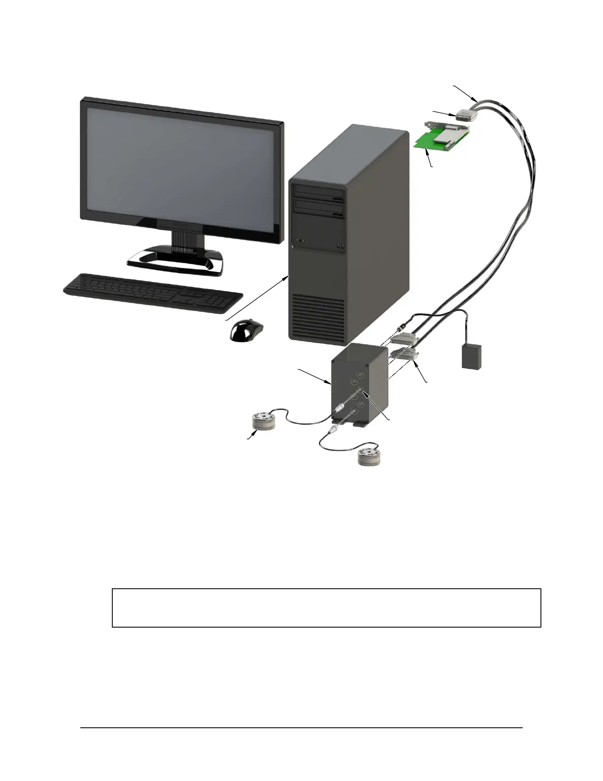
Figure 4.7—Multiple TW Transducers, IFPSMC, and DAQ Card System Installation
Desktop running DAQ Software [1,6]
(9030-05-1001 Software)
[1] PCI DAQ Card
(9105-M1PCI6225)
Multi-sensor Interface Box [2,4,5]
(9105-IFPSMC-6 Shown)
TW Transducer [5]
(9105-TW-MINI58 Shown)
(2) DAQ Cables [2, 3b]
(9105-C-SHC6868EPM-1)
[5] Transducer Connectors
VHDCI Connector [3b]
[2] D-Type Connector
Note: [#] indicates the step number
3. Depending on the DAQ Device and DAQ cables being installed, one of the following connection
methods may be applied:
• If DAQ cables are equipped with a 68-pin D-Type connector, attach the connectors to the DAQ
device and tighten the jackscrews on the connector to insure a good electrical connection.
• If DAQ cables are equipped with a 68-pin VHDCI connector, attach the connectors to the DAQ
Card and tighten the jackscrews on the connector to insure a good electrical connection.
• If the DAQ cables have an unterminated ends, insert the unterminated wires into the desired screw
terminals on the DAQ device and tighten the set screw to ensure good connection.
NOTICE: If you are not using a National Instruments DAQ board with mass termination, you
will have to provide your own connector at that end of the cable. See Section 4.5—Electrical
Connection Information for connection information.
 Loading...
