Manual, F/T Sensor, Data Acquisition (DAQ) Systems
Document #9620-05-DAQ.indd-20
Pinnacle Park • 1031 Goodworth Drive • Apex, NC 27539 • Tel: 919.772.0115 • Fax: 919.772.8259 • www.ati-ia.com • Email: info@ati-ia.com
31
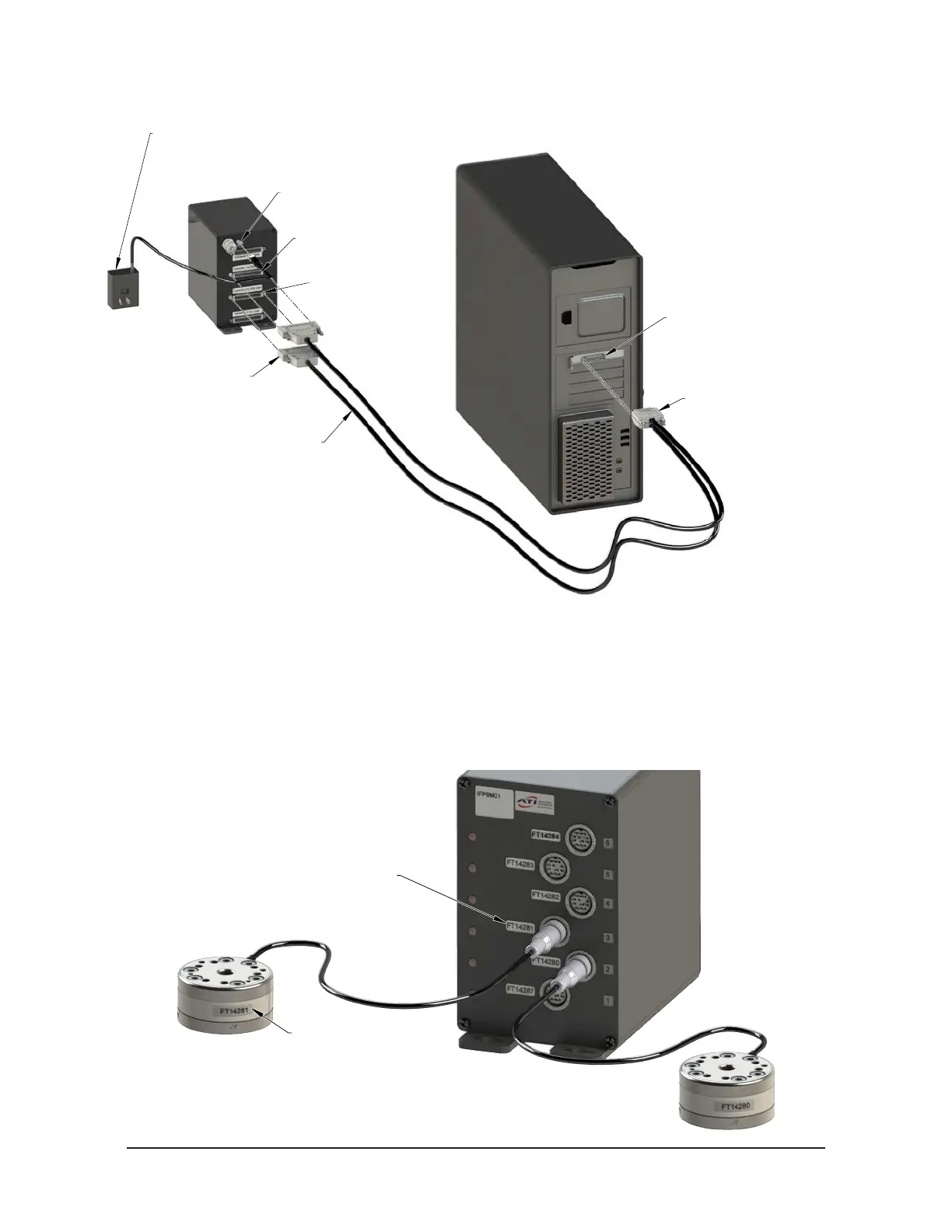
Figure 4.8—Rear view of Multiple TW Transducers, IFPSMC, and DAQ Card System Installation
[4] Power Supply
Connector
[2] Connector 1
to DAQ Card
[2] Connector 0
to DAQ Card
(2) DAQ Cables [2, 3b]
(9105-C-SHC6868EPM-1)
[4] 9105-C-PS-IFPSMC
IFPSMC Power Supply
(Included with Multi-sensor Interface Box)
[1, 3b] PCI DAQ Card
(9105-M1PCI6225)
D-Type Connector [2]
[3b] VHDCI Connector
Note: [#] indicates the step number
4. Plug 12 V wall mount Power Supply into outlet and connect the power supply cable to the power supply
connector on the back of the IFPSMC box.
5. Connect the male connector on the transducer cable to the appropriate connector on the front of the
IFPSMC box. Note: The serial number label on the transducer must match the serial number label on the
IFPSMC Box connector it is plugged into. Refer to Figure 4.9.
6. Refer to Section 4.4—Install the F/T Demo Software to complete the installation.
Figure 4.9—Match the Serial Number Labels from the Transducer and the IFPSMC Box Connectors
[5] Transducer Serial
Number Label
IFPSMC Box Connector [5]
Serial Number Label
 Loading...
