Manual, F/T Sensor, Data Acquisition (DAQ) Systems
Document #9620-05-DAQ.indd-20
Pinnacle Park • 1031 Goodworth Drive • Apex, NC 27539 • Tel: 919.772.0115 • Fax: 919.772.8259 • www.ati-ia.com • Email: info@ati-ia.com
71
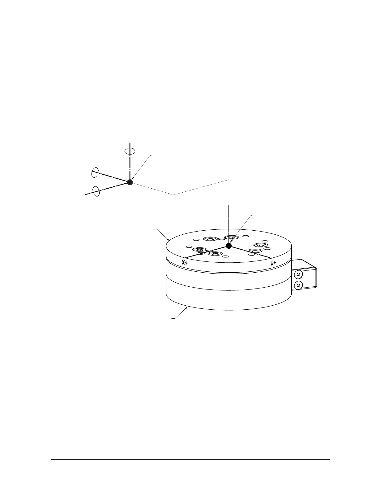
Rotation allows the customer to rotate the axes while maintaining the frame origin. Figure A.2
shows the direction of rotation about the axis. Rotation is measured in radians.
When a value is entered for RX, RY, or RZ the following will result:
• RX value will rotate Y and Z about X in the direction shown (see Figure A.2).
• RY value will rotate X and Z about Y in the direction shown.
• RZ value will rotate X and Y about Z in the direction shown.
In a tool transformation, the order of the rotations is critical. The X-rotation occurs rst, followed
by rotation about Y (in its new orientation), then Z. Therefore, rotations MUST be expressed in this
order
Figure A.2—Rotating Reference Frame
Z+
X+ Y+
X-Y-
Z-
X+
This example shows
a rotation of 1.571 radians
of the X axis.
Y+ Axis
after X Rotation
Z+ Axis
after X Rotation
Sensing Reference Frame Origin
(Customer Applied)
Sensing Reference Frame Origin
(Factory Set)
Tool Side of Transducer
Robot Side of Transducer
 Loading...
