8989
EN
Warnings
Installation
Use
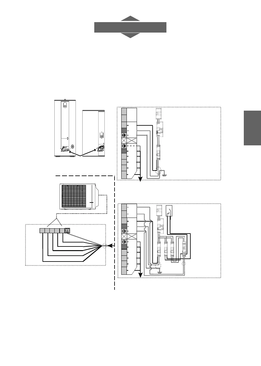
To ensure the tank is protected against corrosion,
Power meter
or
Smart-Grid contact
or
photovoltaic energy
managing device
1 mm²
2A
16A 2A
1C 2C
Main circuit
breaker
16A
2,5 mm²
2,5 mm²
Water heater
terminal box
1 2 3 L
N
N P 11
12
To the outside unit
(7G 1.5 mm²)
230 V single-phase
continuous power
supply
(3G 2.5 mm²)
230V
peak/off
peak hours
7G 1,5 mm²
Outside unit
terminal box
1 2 3 L
N
N P 11
12
To the outside unit
(7G 1.5 mm²)
230 V single-phase
continuous power
supply
(3G 2.5 mm²)
230V
peak/off peak
hours
Outside unit
terminal box
Outside unit
terminal box
2
- Operation during off-peak hours
or with photovoltaic panels
1- Continuous operation or
use of the internal programming
Differential
protection
Circuit breaker
1
2
3
L N
Relais
PLEASE NOTE: In specific cases where it is difficult to install a cable for off-peak hours, the electricity provider’s peak/off peak hours
contact can be replaced by the timer integrated into the unit (Prog. operating range). The off peak schedule sfthen needs to be
programmed (follow diagram 1).
The diagram for the electrical panel shows an electronic meter. For a mechanical meter, use the 230 V power supply for the peak/off
peak hours contact.
For more information, please refer to the section of the instructions entitled "Electrical connection".
the water heater must be permanently connected to the power supply.
Lorem ipsum
4. Commissioning diagram