3.4. Dimension drawing
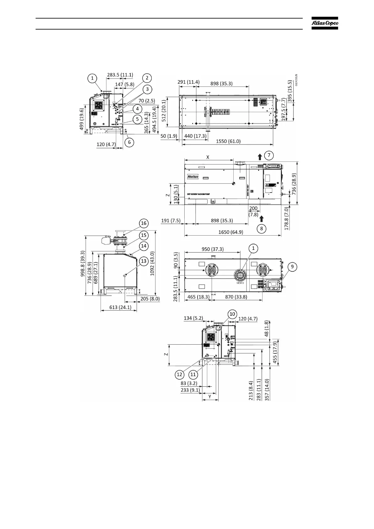
Figure 7 Dimension drawing - DWS 750 VSD+
1. Process inlet 2. Cooling water inlet
3. Spare gas ports 4. Cooling water outlet
5. Gas inlet 6. Exhaust outlet
7. Cooling air outlet 8. Cooling air inlet area cubicle
9. Controller 10. Smart box/Genius box, Antenna
position (optional)
11. Communication cable 12. Mains power inlet
13. Motor cranking access 14. Emergency stop button
15. Adapter (standard) 16. Adapter (standard)/Adapter with
bellow (optional)
Technical data
07/2021 - ©Atlas CopcoPage 181950840208_A