Where,
Q
v
= required cooling air flow (m
3
/s)
N = Nominal motor power of vacuum pump (kW)
T = T
emperature increase in vacuum pump room (°C)
Q
process
= Input thermal power from the process (kW)
Q
HE
= thermal exchange power of the heat exchanger (kW)
Ventilation alternative:
The fan capacity must match the fan capacity of the vacuum pump at a pressure
head equal to the pressure drop caused by cooling air ducts.
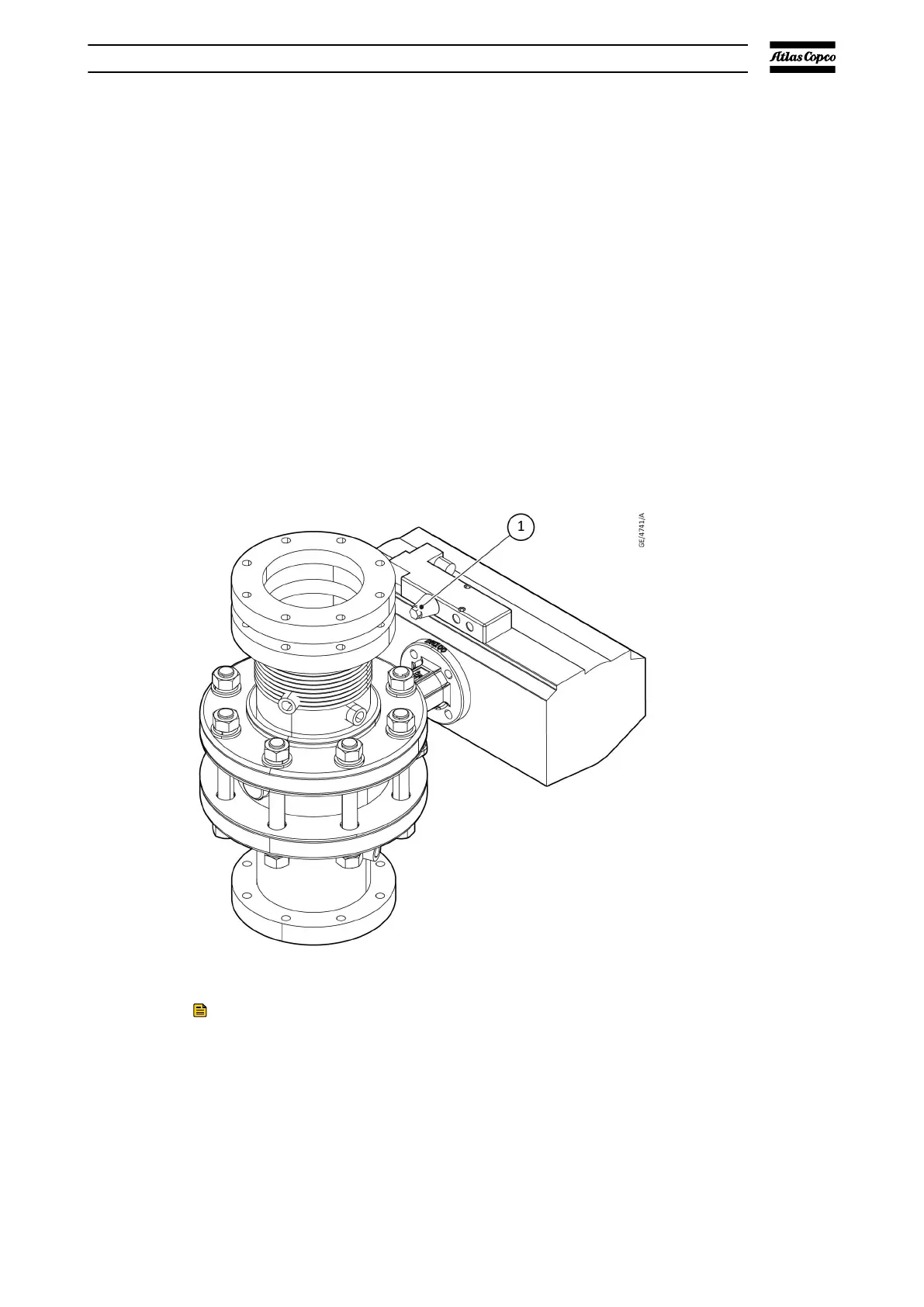
6.3. Compressed air connection
The inlet control valve and blow of
f solenoid are pressure controlled. To operate
they need to be connected to a compressed air source. The pump is supplied
with a push-in coupling for nylon tube diameter 8 x 6 mm.
1. Valve pressure connection1. Valve pressure connection
Note
Effectively isolate the machine from all sources of overpressure and make sure
that the pump system is at atmospheric pressure level before you do
maintenance or repair
.
Properties for the compressed air connection:
▪ The supply pressure should be between 2 bar(g) and 10 bar(g) (29 psi and
145 psi)
Installation
07/2021 - ©Atlas CopcoPage 841950840208_A