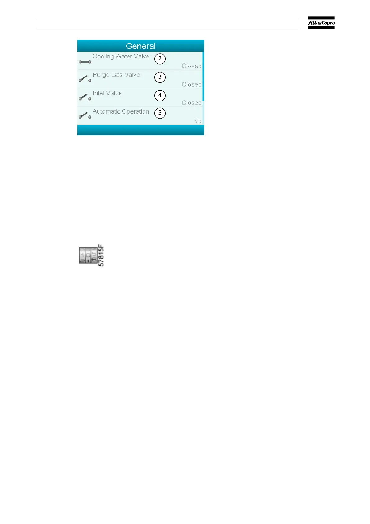
1. Outputs 2. Cooling Water Valve
3. Purge Gas Valve 4. Inlet Valve
5. Automatic Operation
1. Outputs 2. Cooling Water Valve
3. Purge Gas Valve 4. Inlet Valve
5. Automatic Operation
▪ The screen shows a list of all the output switches and their related icons and
readings.
▪ If an input has a warning or shutdown, the initial icon is replaced by the
related warning or shutdown.
4.8. Counters
Menu icon, counters
Function
To show:
▪ the running hours
▪ the number of motors starts
▪ the number of hours that the regulator has been powered up
▪ the fan starts
▪ the emergency stops.
Procedure
Start from the Main screen (refer to
Main screen on page 33):
▪ Use the Scroll keys to move the cursor to the Menu action button.
▪ Push the Enter key
. The screen that follows is shown:
Elektronikon® graphic controller
07/2021 - ©Atlas CopcoPage 421950840208_A