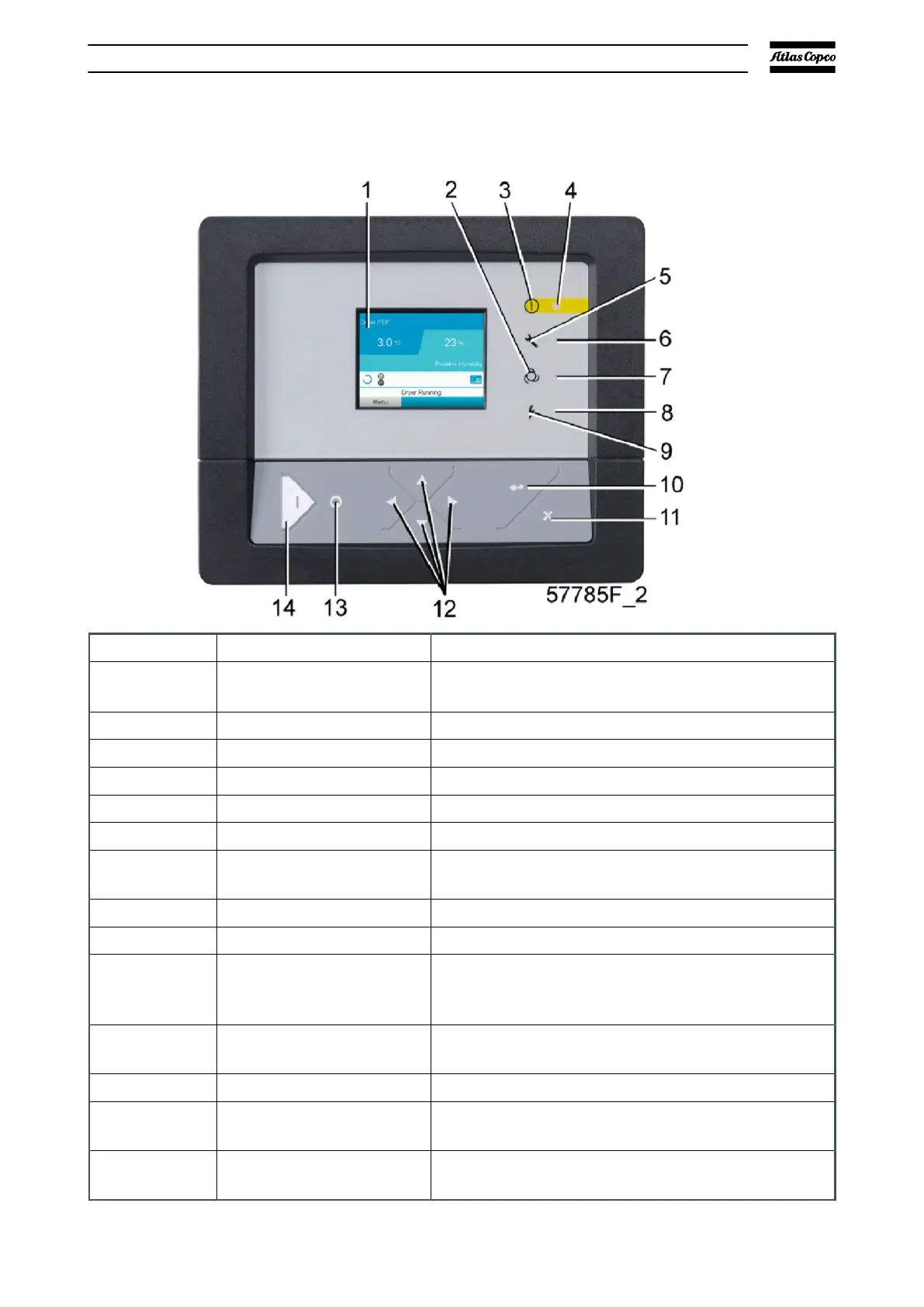
4.2. Control panel
Figure 9 Controller
Reference
Designation Function
1 Display
Shows the status of the pump and the different
icons to move through the menu.
2 Pictograph Automatic operation
3 Pictograph General alarm
4 General alarm LED Flashes if a shutdown warning condition occurs.
5 Pictograph Service
6 Service LED Flashes if a service is necessary.
7 Automatic operation LED
Shows that the controller automatically controls
the pump.
8 Voltage on LED Shows that the voltage is switched on.
9 Pictograph Voltage on
10 Enter key
To select the parameter shown by a horizontal ar-
row
. Only the parameters followed by an arrow
that point to the right can be changed.
11 Escape key
To go to previous screen or to end the current ac-
tion.
12 Scroll keys Keys to move through the menu.
13 Stop button
To stop the pump. Automatic operation LED goes
out.
14 Start button
To start the pump. Automatic operation LED
flashes to show that the controller is in operation.
Elektronikon® graphic controller
07/2021 - ©Atlas CopcoPage 301950840208_A