FlexiROC T35 R/T40 R 9 Angle instruments
121 No: 3171473547.1 en
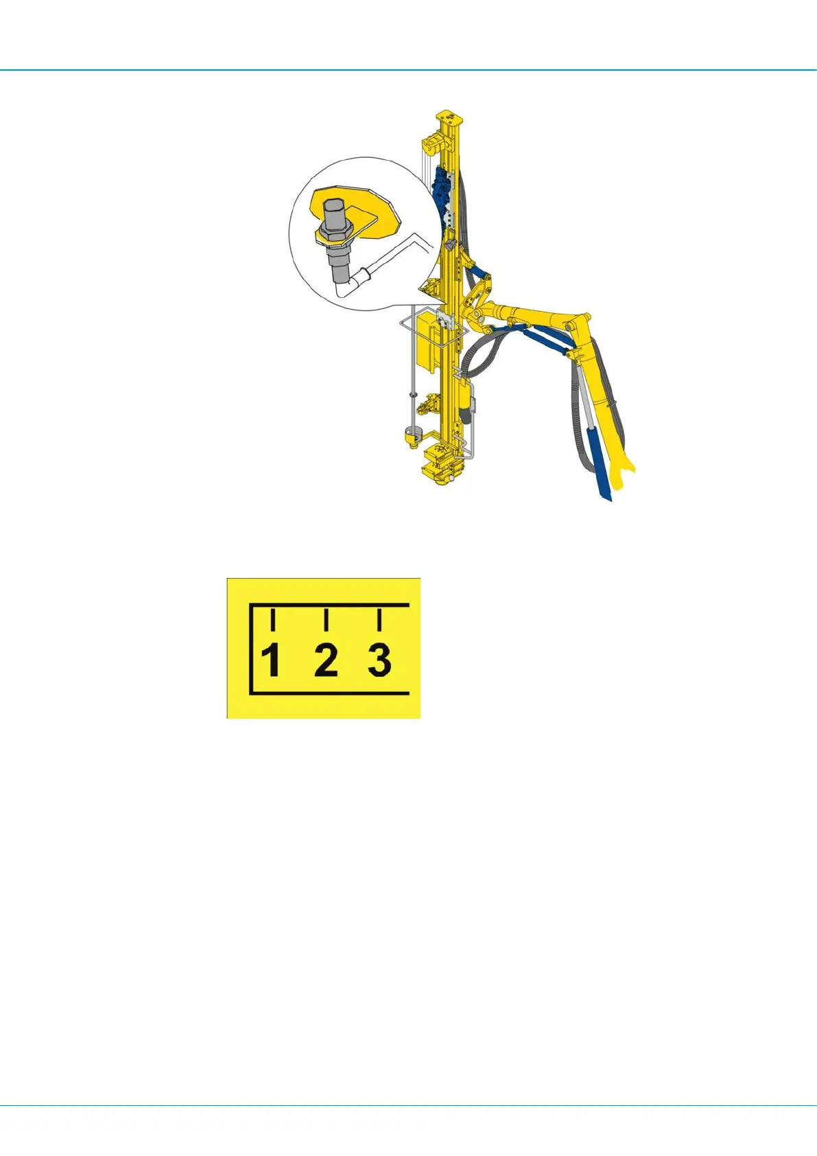
Calibration sensor.
3.
The symbol for "Calibrate length sensor" in the status bar of the display will be extin-
guished once the length sensor is calibrated.
Warning symbol "Length sensor not calibrated".
9.1.7 Operation
1.
Move the rig to the drill site and set it up in the desired position.
2.
Select a reference point and turn the sight so that the arrow points towards the refer-
ence point. The reference point should be as far away as possible (at least 2 km) if it
does not lie in direct line with the row of holes in order to minimise angle error. If the
reference point lies in line with the row of holes, it can be as close as 10 m from the
last hole of the row without any angle errors arising.
3.
Set the desired hole inclination front/back or left/right.
4.
Position the feed beam so that the red line in the graphic is reduced to a red dot in the
centre. Once this has occurred, the desired angle value is the same as the actual
value.
5.
Press the feeder spike against the ground by using the feed extension.
 Loading...