FlexiROC T35 R/T40 R 5 Controls
48 No: 3171473547.1 en
m Primary field
The push buttons a - c provide direct access to the selected graphic presentation. To se-
lect a graphic presentation: select the desired presentation using the arrow keys and con-
firm by pressing the Enter key.
!
NOTE: Switching between directional instrument and drilled length (F2 and F3) takes
place automatically from the remote control box transmitter. When drilling mode (S130
f) is selected the drilled length is displayed. When positioning mode is selected (S130
h) the directional instrument is displayed.
Status field symbols
The status field on the engine display shows information to the operator in the form of col-
oured symbols. The information shown is an indication or a warning. Indications are green
while warnings are either yellow or red.
n Green - Indication that a specific function is activated, e.g. compressor loaded.
n Yellow - Warning to indicate that something is not in its normal state and that the op-
erator must undertake some form of remedy. Machine not in acute danger of malfunc-
tion.
n Red - Warning, indicates that something is in a critical condition. The engine is
switched off when there is significant risk of machine breakdown.
!
NOTE: Yellow symbols can become red if the status of the fault worsens.
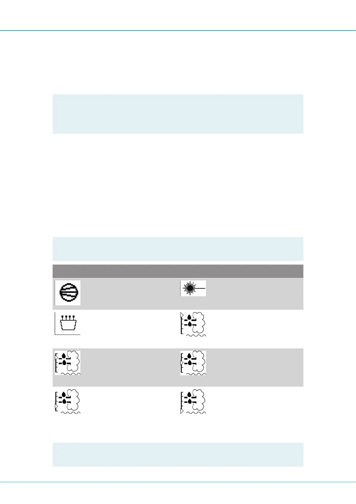
Symbol Description Symbol Description
Compressor
Compressor loaded
Laser status
indicates laser status*
Radio system
Radio system active
DEF level > 80%
Indicates that the DEF
(Diesel Exhaust Fluid)
level is > 80 %
DEF level < 80%
Indicates that the DEF
(Diesel Exhaust Fluid)
is < 80%
DEF level < 60%
Indicates that the DEF
(Diesel Exhaust Fluid)
is < 60%
DEF level < 40%
Indicates that the DEF
(Diesel Exhaust Fluid)
is < 40%
DEF level < 20%
Indicates that the DEF
(Diesel Exhaust Fluid)
is < 20%
Table28: Green symbols (Information symbols)
!
NOTE: *) Grey background indicates selection of laser plane. Green background indic-
ates hitting the laser plane.
 Loading...